Please Log in or Create an account to join the conversation.
garfi3ld wrote: your about to post new pics!! woot

Please Log in or Create an account to join the conversation.
Please Log in or Create an account to join the conversation.

Please Log in or Create an account to join the conversation.
Please Log in or Create an account to join the conversation.
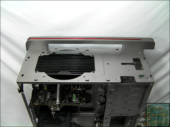
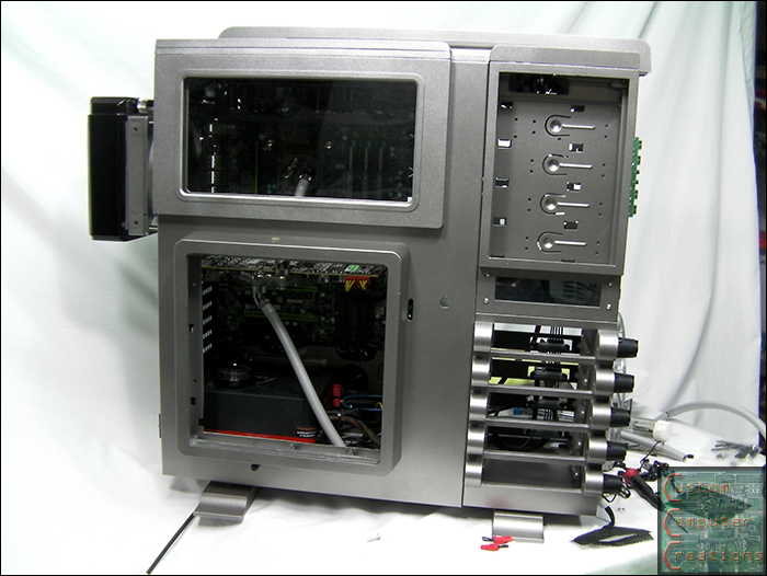
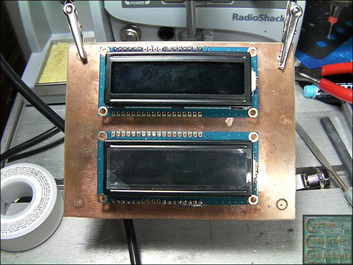
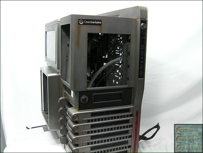
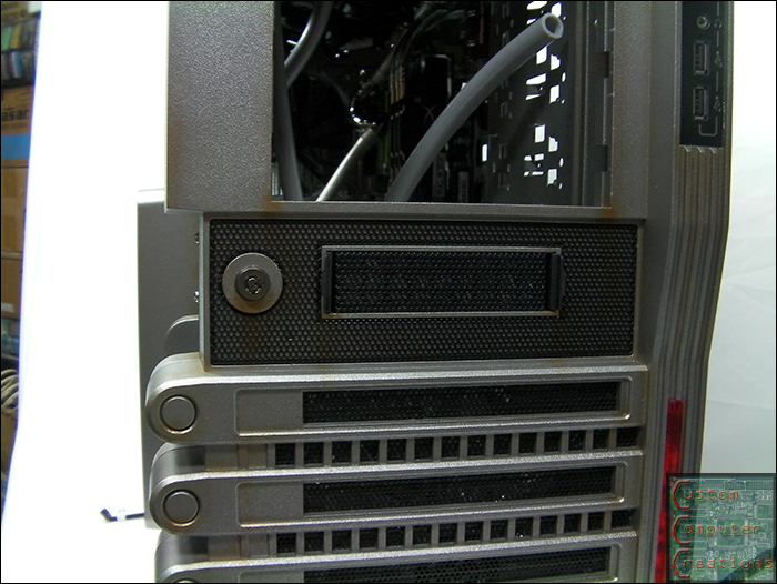
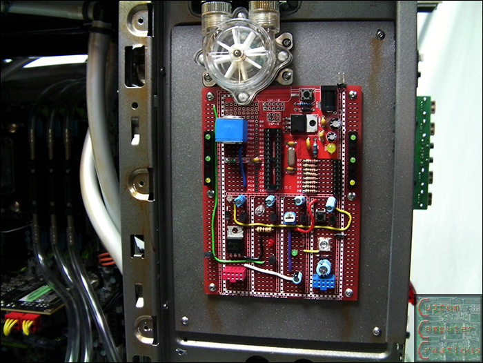
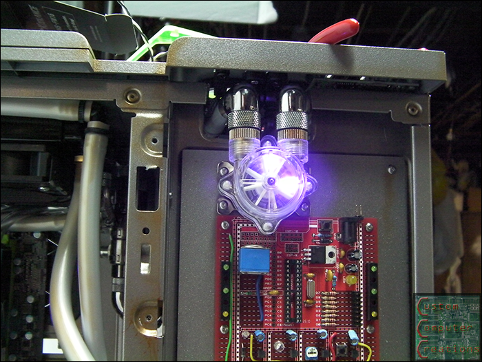
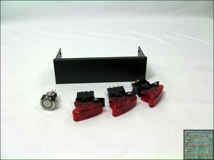
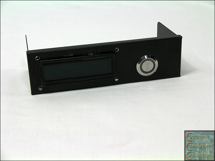
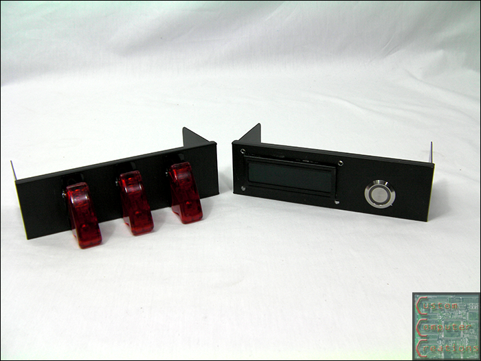
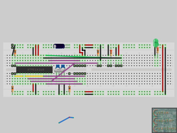
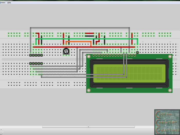
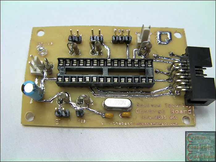
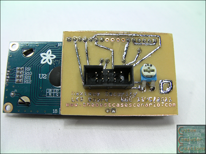
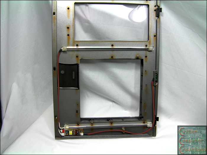
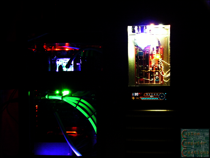
Plague wrote: that looking awesome can't wait to see the LCD screen in the front. great work man.
Please Log in or Create an account to join the conversation.
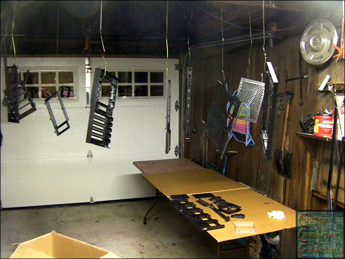
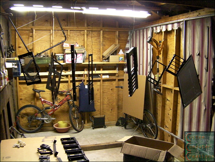
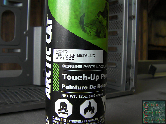
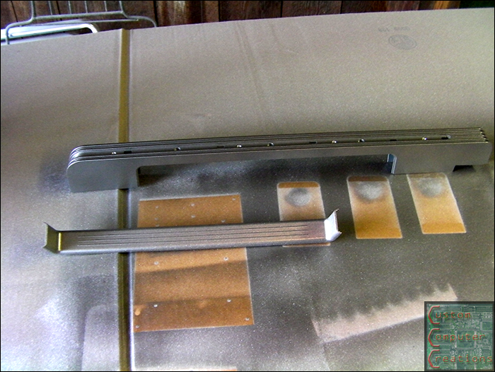
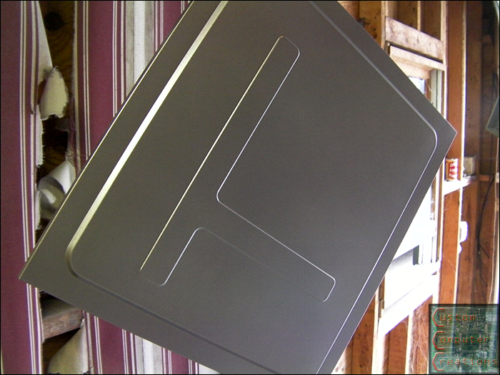
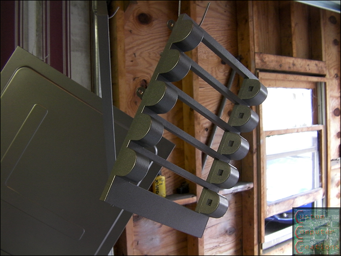
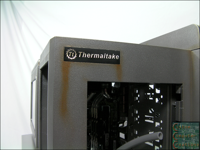
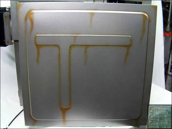
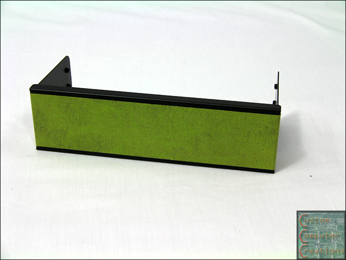
Thanks again to Auto Air Colors for providing the paint!!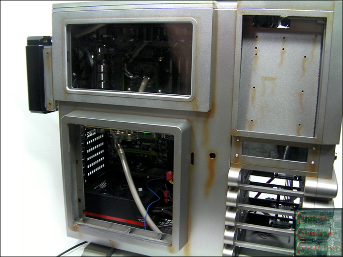
Please Log in or Create an account to join the conversation.
Please Log in or Create an account to join the conversation.
Please Log in or Create an account to join the conversation.
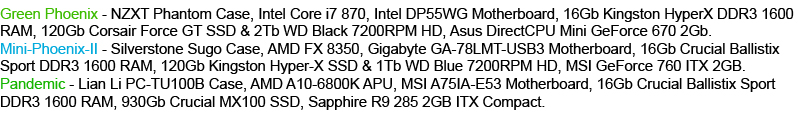
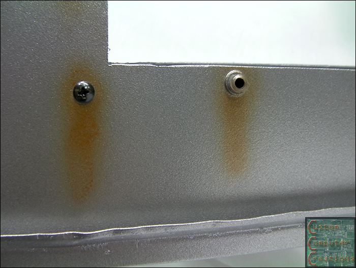
Wingless92 wrote: This mod is retarded, retardedly cool! Every update looks better and better. I am really liking the rustic look. Looks like you let it sit outside for a couple of months.
Please Log in or Create an account to join the conversation.

Please Log in or Create an account to join the conversation.
Please Log in or Create an account to join the conversation.
 I'd send the mod by itself, but it's my primary rig so not having it for a week or more (with trucking) can't happen lol.
 Please Log in or Create an account to join the conversation.
Please Log in or Create an account to join the conversation.
Please Log in or Create an account to join the conversation.
Please Log in or Create an account to join the conversation.
Please Log in or Create an account to join the conversation.
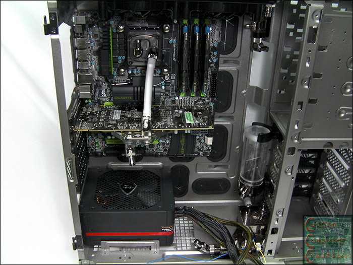
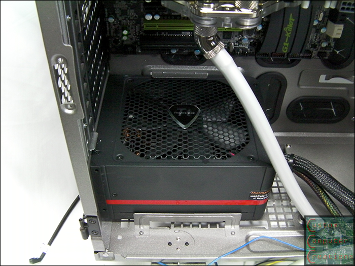
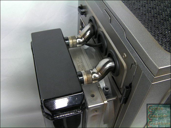
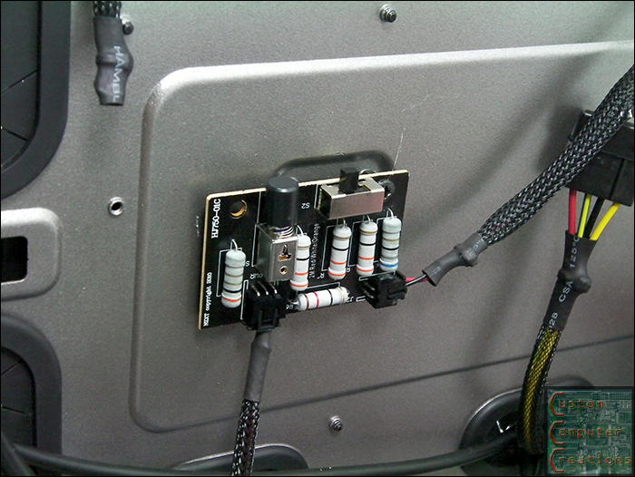
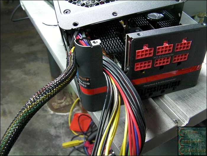
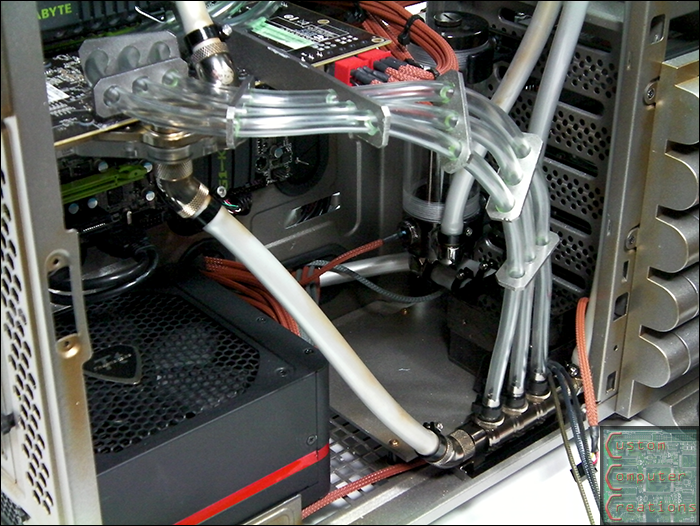
Plague wrote: looking very cool. I need look at modding my PSU that way. Can't wait to see it all together and running.
")
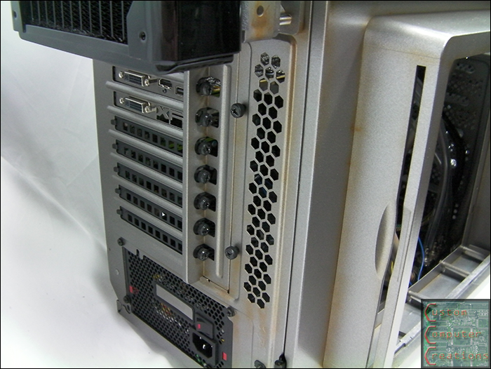
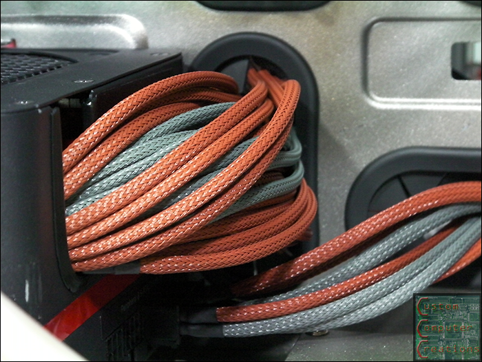
Arxon wrote: where do you find the wire sleeves at?
Please Log in or Create an account to join the conversation.
Please Log in or Create an account to join the conversation.
Please Log in or Create an account to join the conversation.
Please Log in or Create an account to join the conversation.
Please Log in or Create an account to join the conversation.
Please Log in or Create an account to join the conversation.
Please Log in or Create an account to join the conversation.
Please Log in or Create an account to join the conversation.
Please Log in or Create an account to join the conversation.
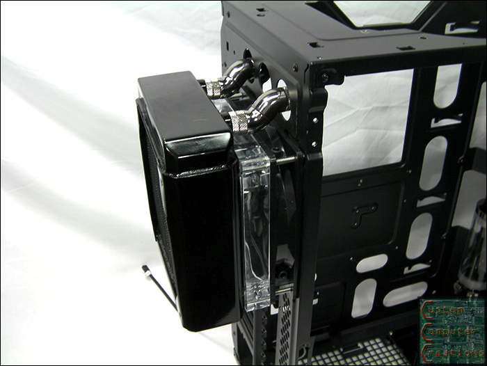
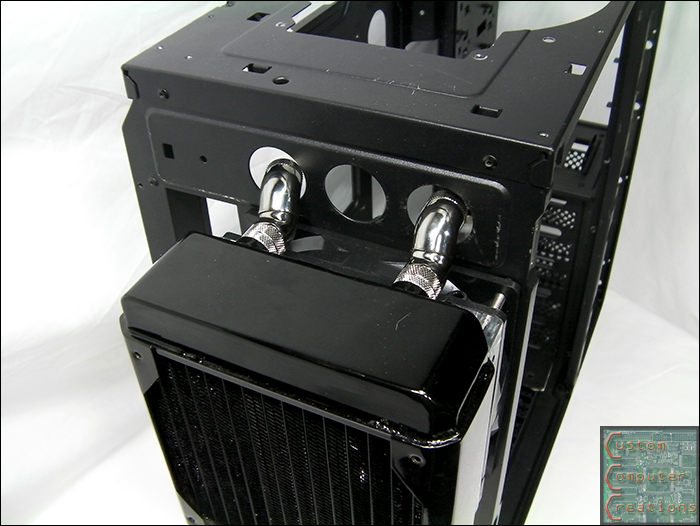
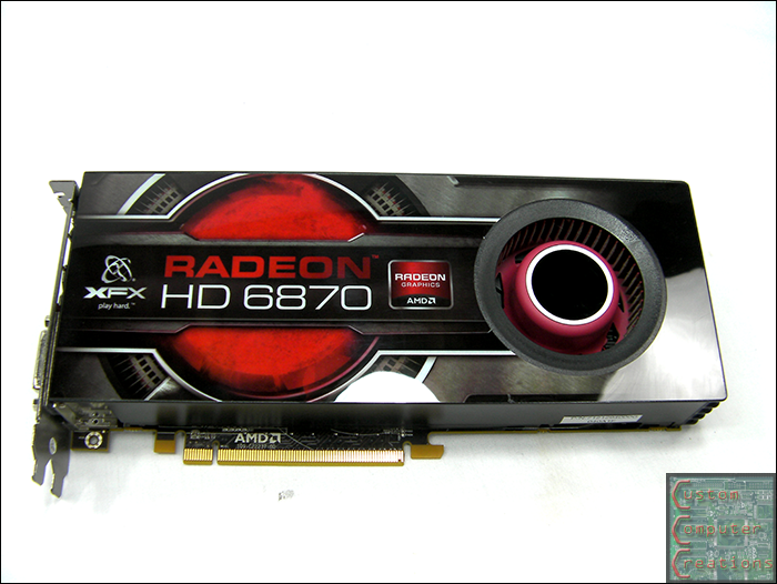
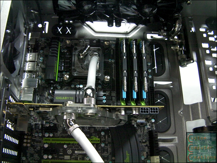
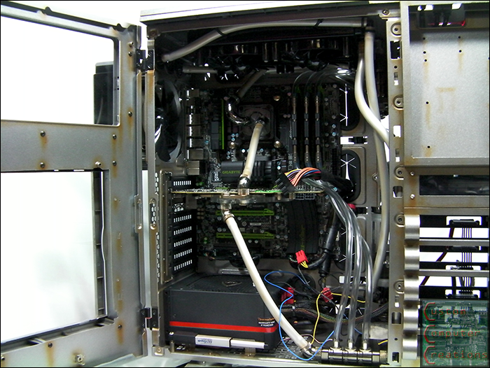
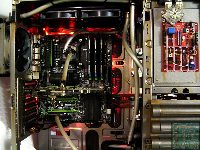
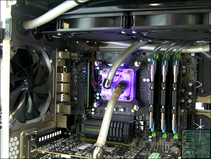
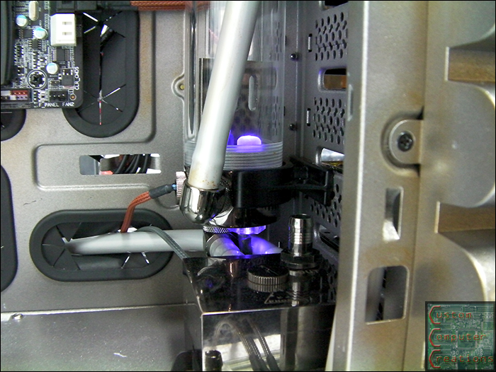
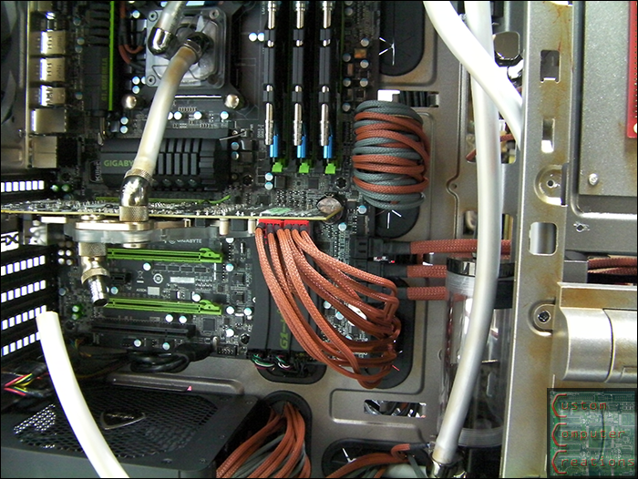
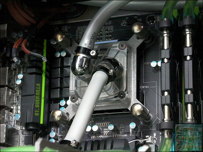
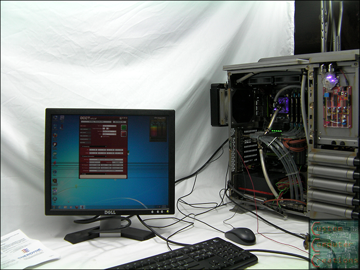 I'm getting ~34ºC idle and topping out at ~48ºC under Hyper Pi, OCCT and Prime95.
 Please Log in or Create an account to join the conversation.
Please Log in or Create an account to join the conversation.
Please Log in or Create an account to join the conversation.