So you have had a shiny new 3D printer for a few months, your house now is full of little plastic tchotchkes. There are Little Yoda heads in the living room, some benchy boats in the bath, and an R2D2 on your desk. What’s next? You can buy fancy filaments with metal powders embedded in them so you can make your gnomes rusty or green but they’re still plastic. How does one make something metal with a 3D printer? You can spend a huge sum of money and buy a printer that can sinter metal powders together. Unless you’re NASA or SpaceX that is a lot of money. Sure, you could slap a MIG welder nozzle on your printer but that is not very precise and would take a lot of tinkering to get something useful out of it. Instead of going high tech, let’s go low tech. Casting liquid metal into sand molds is a process humans have been doing for centuries. What if you used a 3D printer to create the mold patterns for the sand in a few hours instead of the day(s) it would have taken to do by hand?
Article Name: Casting 3D Printed Parts
Written by: Bruce Maley
Pictures by: Bruce Maley
Our Amazon Affiliate Link: HERE
Safety Warning
Before we get started, I would like to stress the proper use of P.P.E. (Personal Protective Equipment). The temperatures worked with when casting can cause 2nd and 3rd degree burns in just seconds. So assuming you will pull away fast enough if things go wrong just isn’t going to work. Proper flame-retardant shirts and pants, heavy leather gloves and shoes, as well as eye and ear protection are all required. You should have water buckets and fire extinguishers within feet of the furnace at all times, don’t assume just because they aren’t visible in our photos that they aren’t there. If you try this at home, you do so at your own risk.
Design and Printing
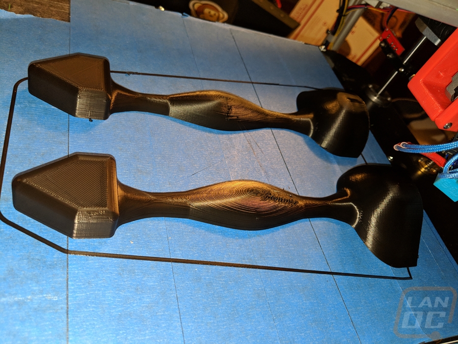
Like all 3D prints, we start on the computer in a CAD (Computer Aided Design) software. In this, case Auto Desk Fusion 360. I have designed a pattern for a sand rammer. It’s a type of hammer that is used to compress the sand in a mold around the patterns.
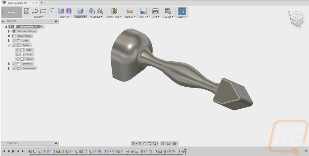
The pattern is split in half to give us 2 flat faces. There is also a set of alignment holes for pins in them.
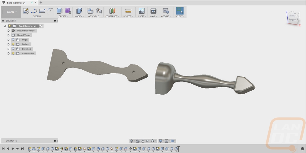
From the drawings, an STL file for each half is created. The STL files are then run through a slicing program to generate the Gcode that drives the 3Dprinter.
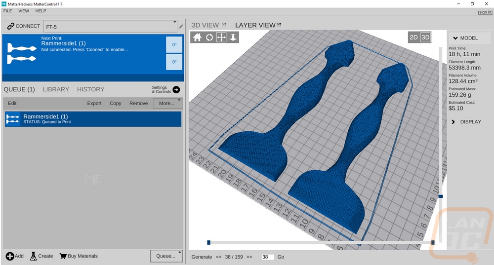
Both halves of the pattern were printed at the same time.
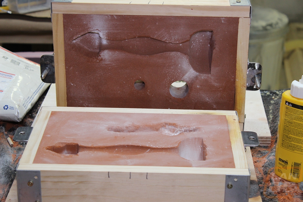
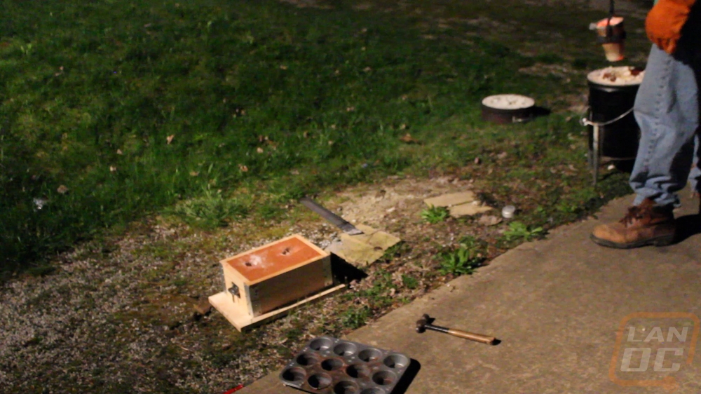
Molding
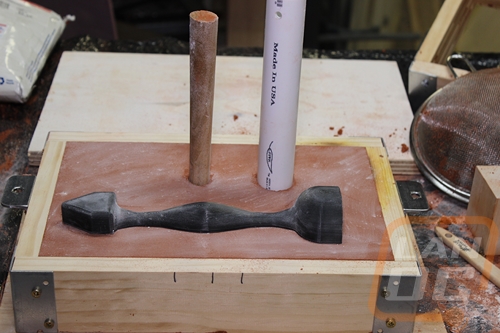
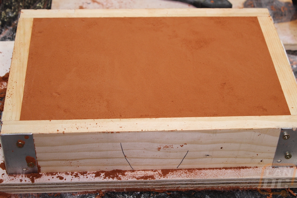
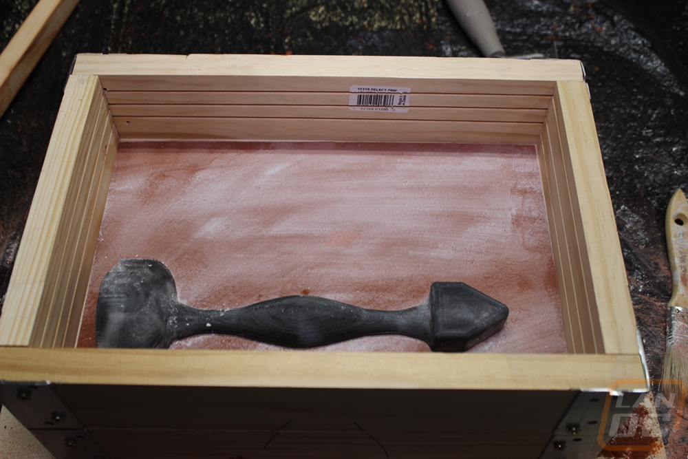
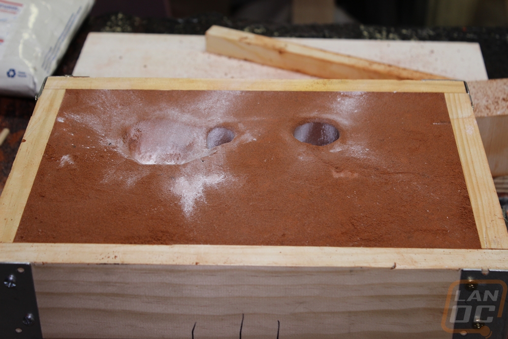
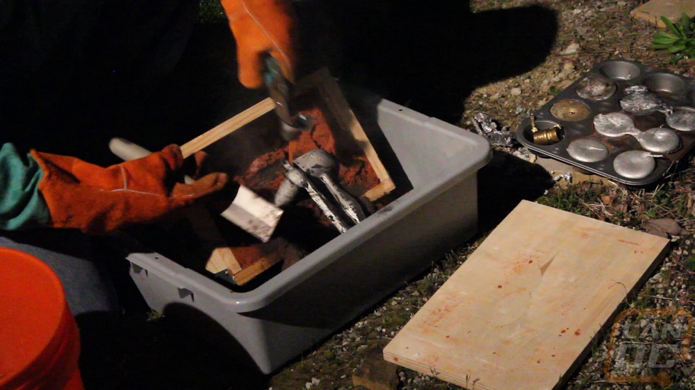
The next part of the process is where we start getting dirty. The bottom pattern is placed flat side down on a flat board. The flask is now set around the pattern. The flask is the wooden or metal box that the mold is made in. It has two parts the drag (bottom) and the cope (top).
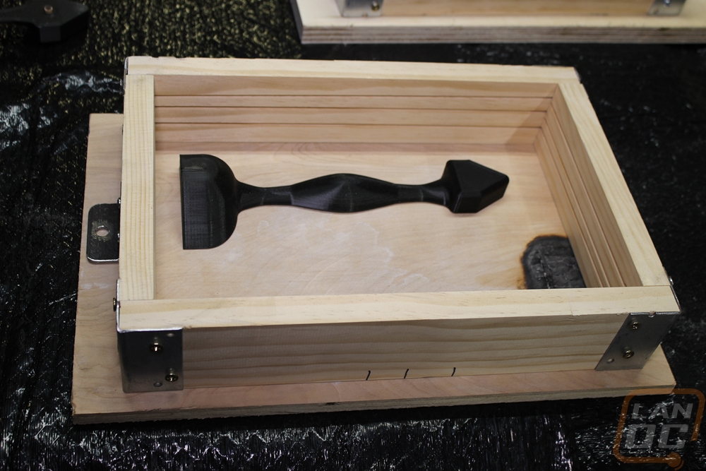
The part and the board are coated with a parting agent (I am using talc or chalk). Excess agent is then dusted off the part with a soft brush. The parting agent keeps the sand that will be added next from sticking to the pattern and the two halves of the mold.
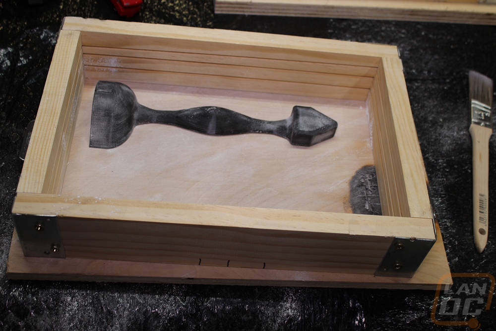
The sand that gets added now is called petrobond. It is a mix of fine sand, clay (treated to absorb oil), and a very tiny amount of oil to help it all stick together. The sand is sifted through a screen to only allow the fine unclumped sand to touch the pattern. This is only done for the bit of sand that is next to the pattern. Once the pattern is covered sufficiently it’s packed down lightly and more sand is dumped into the drag. The sand is packed and added until the drag is full.
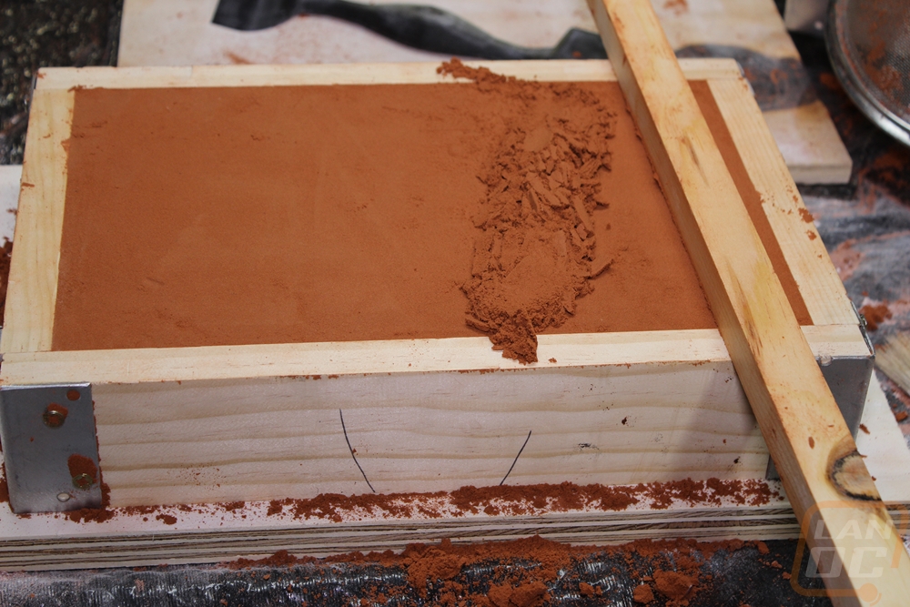
Striking off the drag is the last step in this process.
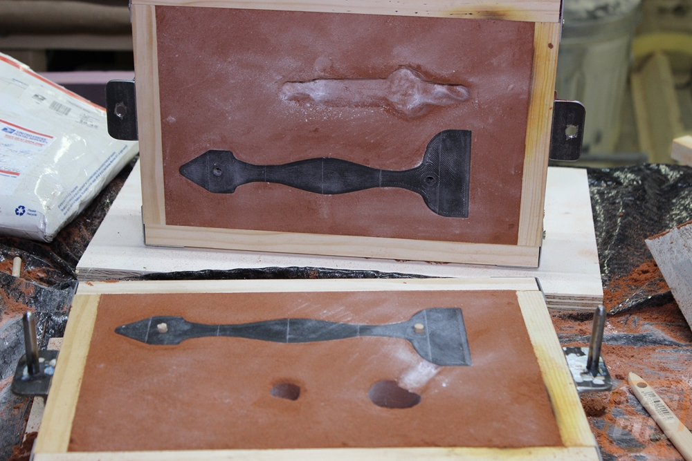
The drag is flipped over and the cope is set on top. The second pattern half is attached to the first via the pins.
The process of covering the pattern in the parting agent, brushing, sifting sand, and packing is repeated. Two tubes were added when I did this. The smaller tapered one is the sprue, where the metal is poured. The other tube is the riser, where the reservoir of metal goes. This is needed because as the aluminum cools it shrinks the riser will stay molten until after the part has solidified (If we do everything correct).
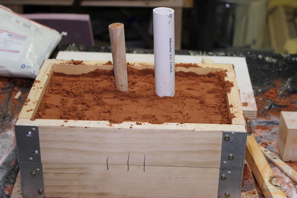
Gating and Runner
Once the cope is fully rammed and struck off, the tapered sprue and riser tube can be removed. With all that complete the mold can now be opened.
The edges around the top of the riser and spure need to be rounded over. A pouring basin needs to be cut in beside the spure.
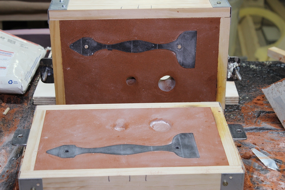
Creating the runners and gating apart is as much an art as a science. I’m covering one way that worked for this part. This is by no means a deep dive into this black art.
A runner is cut into from the sprue to the riser. The runner has extra length to help trap any sand or oxides that get into the pattern. The gates from the runner to the part are cut into the cope. This is done with the pattern in place to help keep the mold cavity from collapsing.
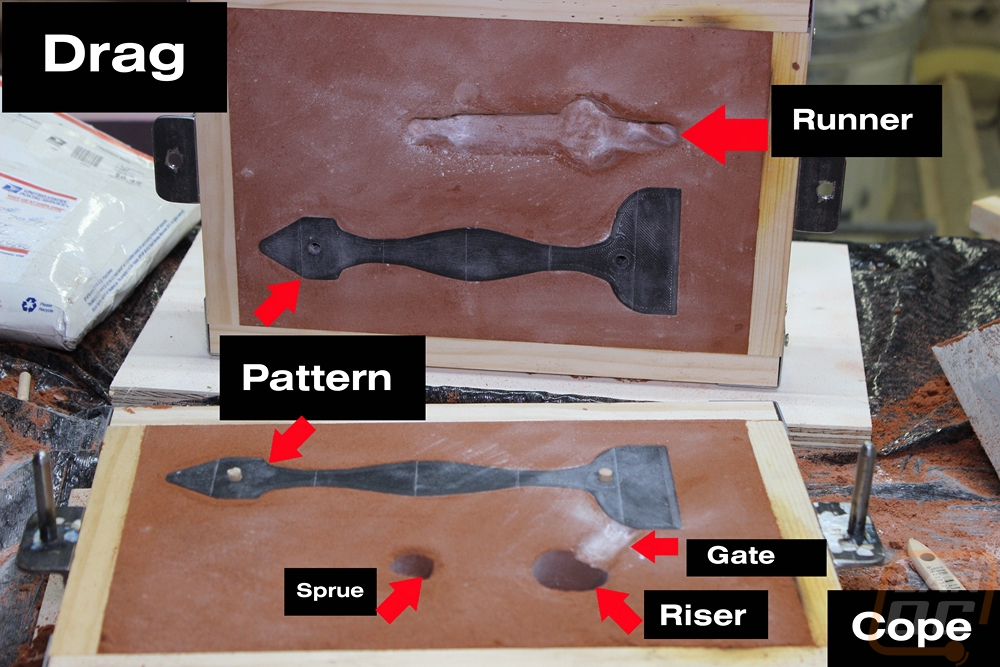
This next Photo has all of the Parts of the mold labeled for clarity.
Removing The Pattern
To remove the pattern halves, a little gentle tapping is required. A couple of screws are screwed into the pin locations and the part lifts out.
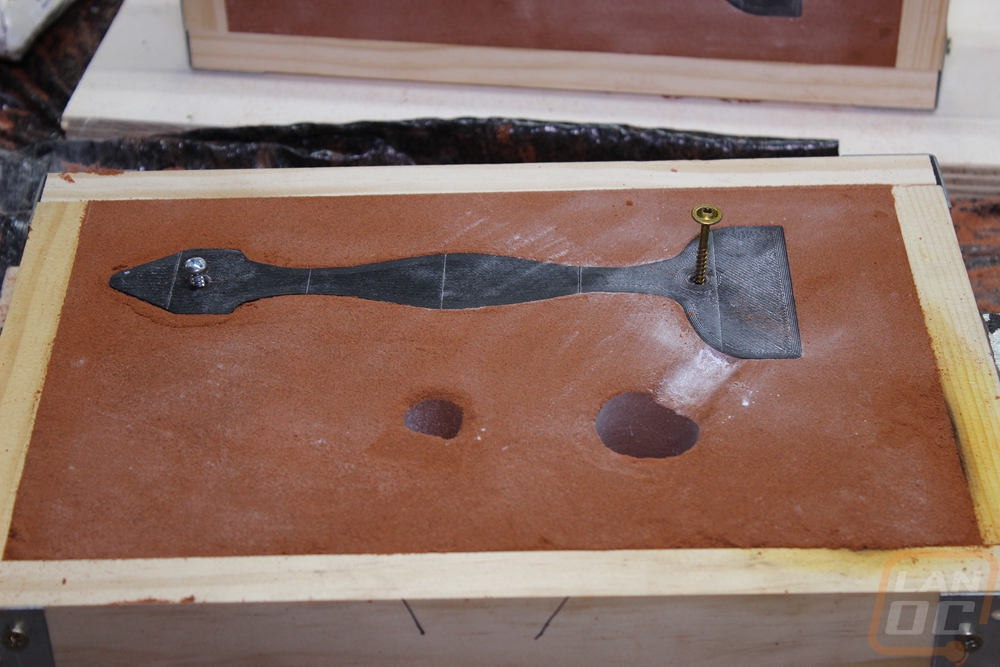
When you remove the pattern sometimes you knock some of the sand loose from the mold. Most of the time you can repair it in the mold. If the defect can’t be repaired, but it in a non-critical place you leave it and grind/machine the extra metal off afterward. When the defect is too large the mold is scraped and you start again. Due to the fact so much time goes into making a mold you do your best to repair them.
Casting Metal
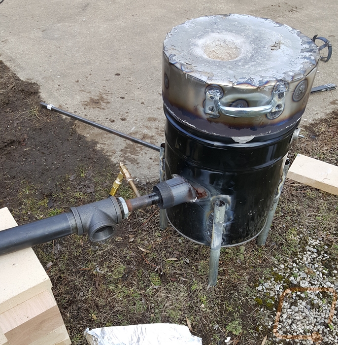
To melt enough metal for this pour, we will need a furnace that can exceed 1200 degrees Fahrenheit. This furnace is a forced air propane homemade unit that is more than capable of hitting the target temperature. We will not be going over the construction of it here, there are a number of good furnace build logs online if you are interested in that. Stay away from any that use plaster of Paris or pearlite. Furnace builds, Furnace builds
 The metal used for this pour is Aluminum. These ingots were made from an aluminum extrusion.
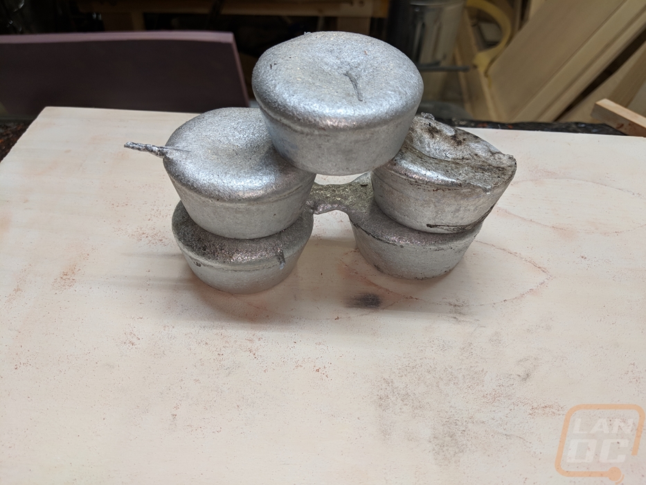
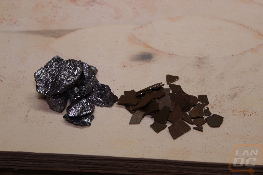
Extrusion is not great for casting because it is missing some trace elements that help it flow smoothly and shrink less. We will be adding a couple of those elements back into the melt today. Silicon and manganese will be added at 10% and 0.2%.
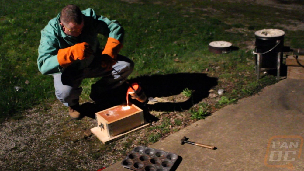
With the furnace going, the aluminum is preheated on the lid to make sure there’s no moisture introduced to the molten pool of metal. Steam expands about 1600 times if it does that at the bottom of a pool of molten metal you will end up wearing it. Once the aluminum has melted, the crucible is pulled from the furnace.
The molten metal is then poured into the pouring basin of the mold in a smooth constant stream.
Once pouring is complete, the mold is left to cool for 15-20 minutes.
Demolding and Finishing
After the aluminum has cooled enough to solidify the sand is removed from around the part.
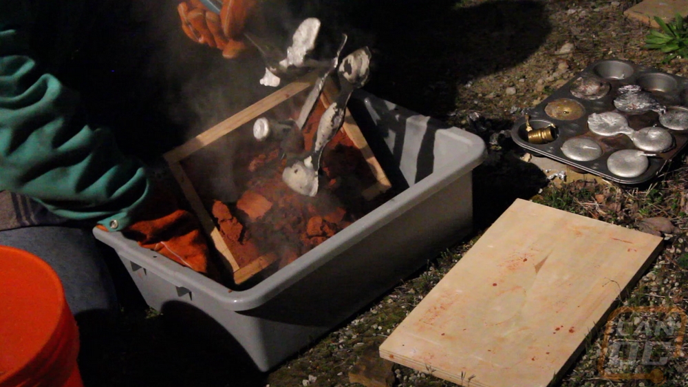
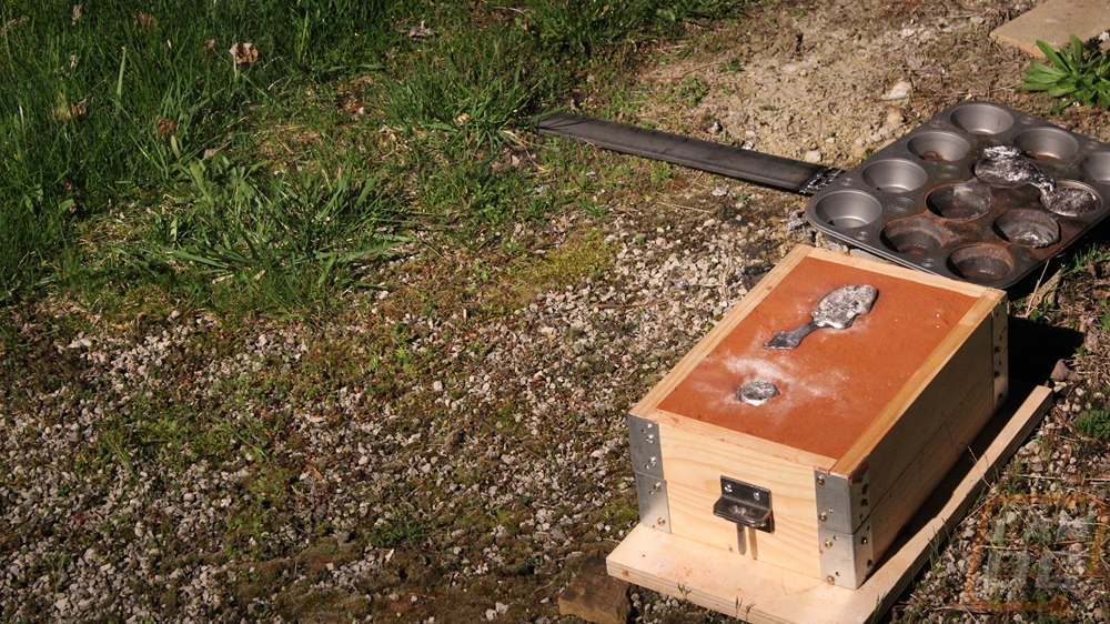
All of the burnt sand is wire brushed off of the part. Care is taken to recover as much of the sand as possible as it can be reused many times.
Once the bulk of the sand is removed the part is rapidly cooled in water. The rough casting is shown here on the molding board.
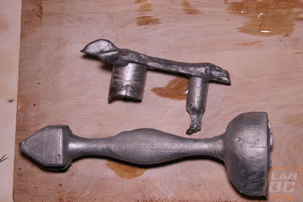
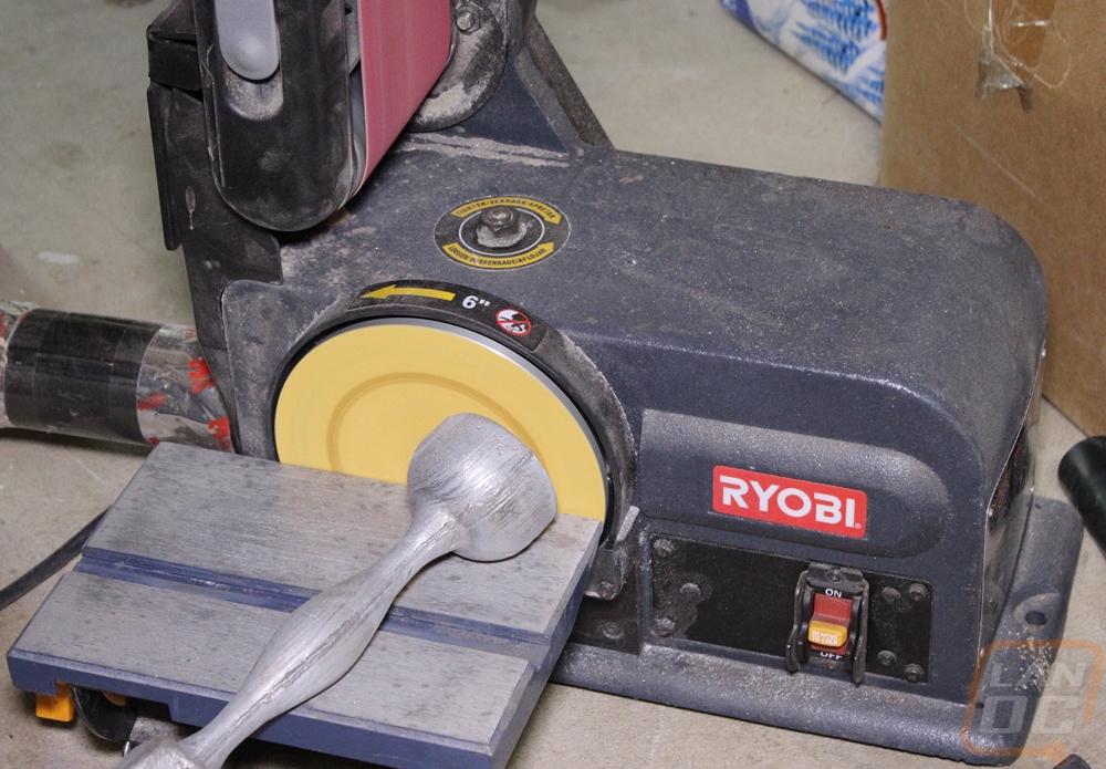
The runner system broke off the part while handling them. With this part, the flashing (the little bit of metal that worked its way through the mold parting line) will be removed with a sander.
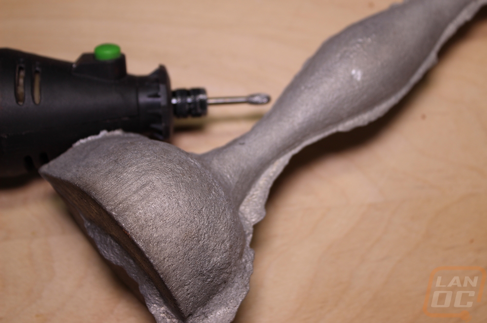
The flat faces will be trued up on the sander. No additional machining is needed.
Wrap up
This is the first time I have cast this pattern. I found a few minor issues that if I were to cast it again I would want to address. The flat faces on the tapered end and the bottom didn’t pull cleanly from the sand. This added time in fixing the mold and finishing the cast part. I took it out for a test spin in the sand.
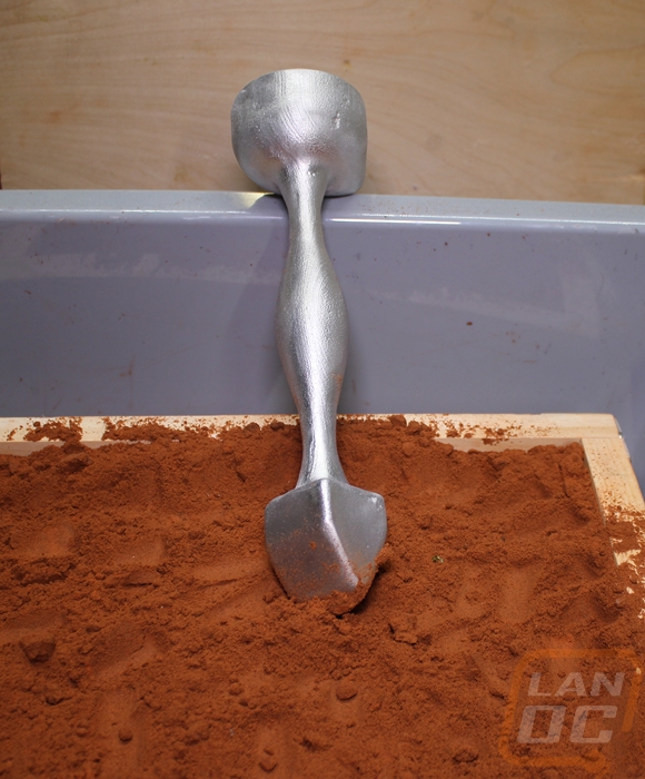
Overall I am happy with the outcome. It has a nice weight of just over 1 Lb. Fits well in the hand and doesn’t fatigue the user. The angled end compacts the sand well as well as leaving the surfaces of the layers textured enough to lock them together. The Flat end speeds the final compression of wide areas. Overall, I’m happy with the outcome.