Board Layout and Pictures
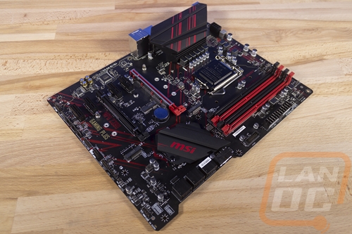
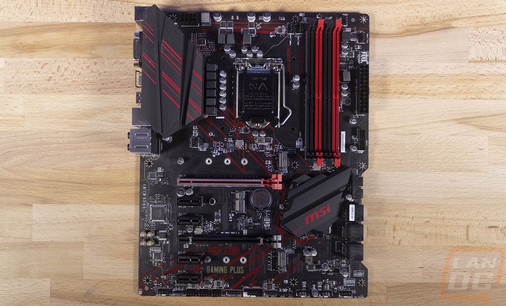
So the Z90 Gaming Plus looks a lot like the previous Z370 Gaming Plus, no big surprises there. It is full ATX with a black PCB and red accents printed on the board and heatsinks. Like I mentioned before, Z370 and Z390 are mostly the same so that makes sense. MSI did improve the heatsink sizes and it looks like they have added a few more power phases as well with the six over on the left and three up top where the Z370 board only had 3 and 3. One thing is for sure though, MSI is still all in on the gaming red and black theme. Overall the board looks a little bare, but that is normal with a full ATX mainstream motherboard. It does have a notched out section on the right side with the SATA ports.
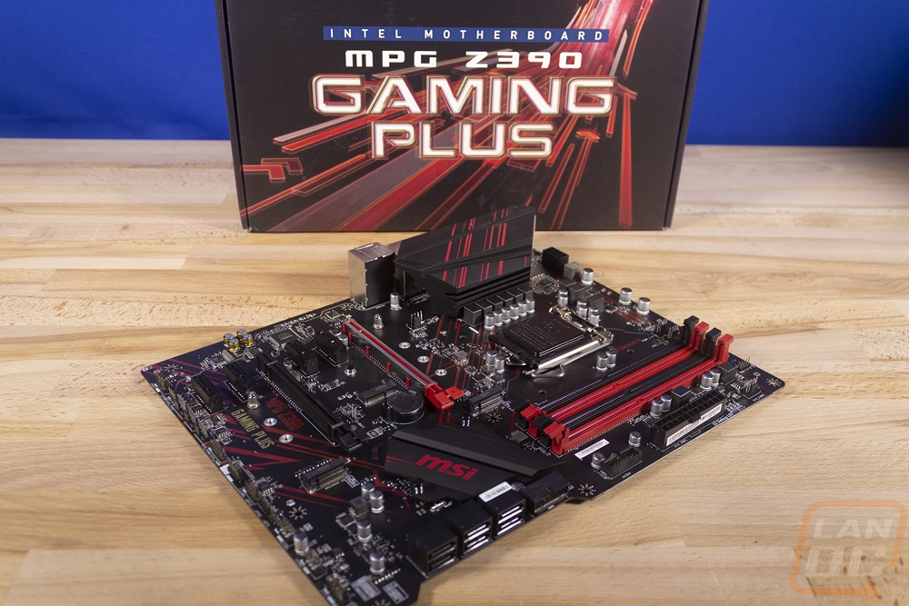
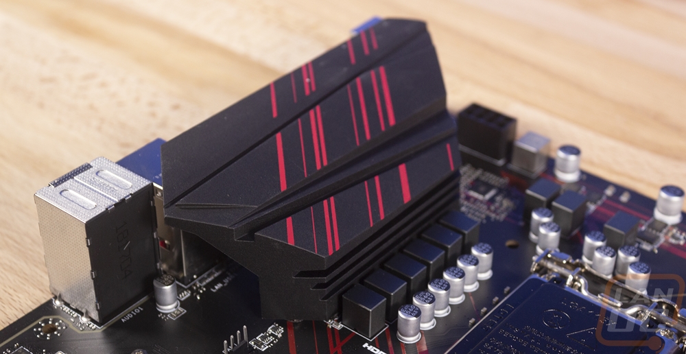
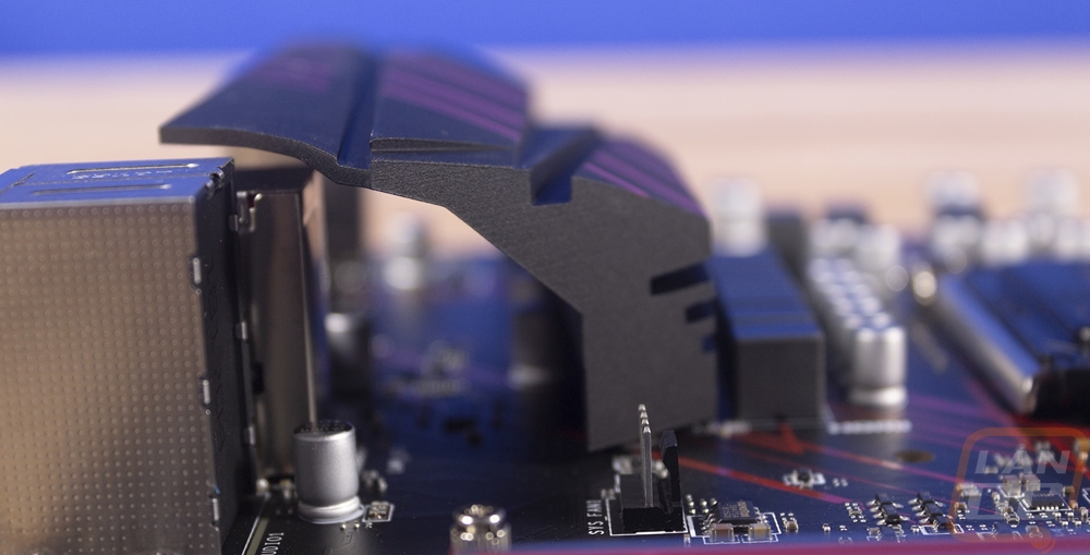
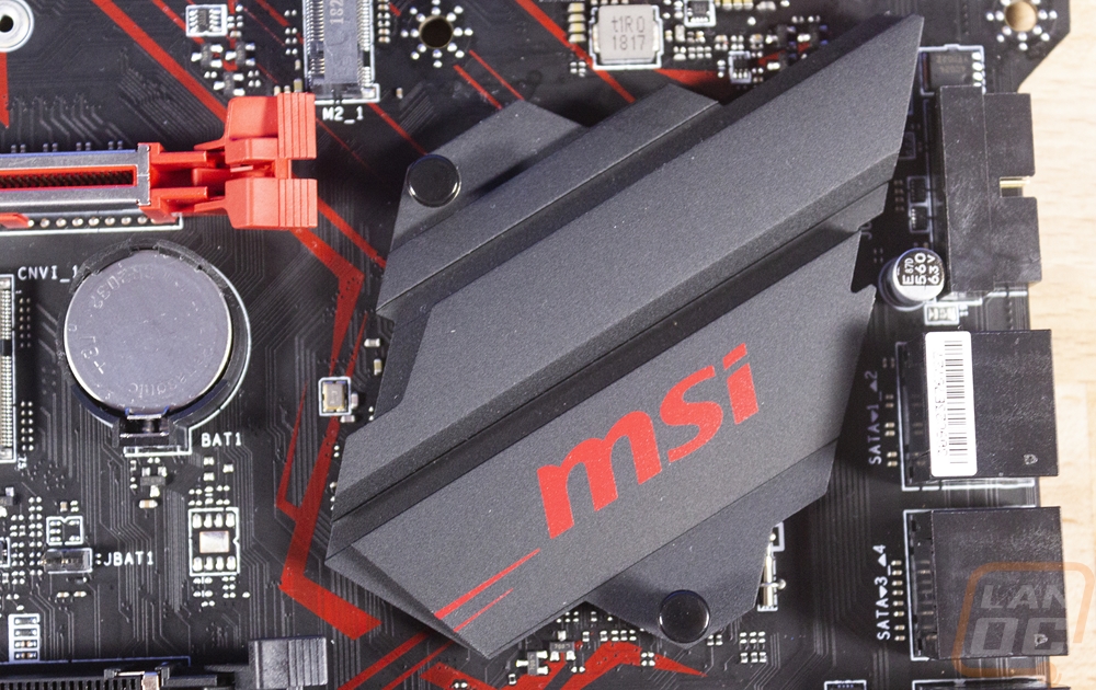
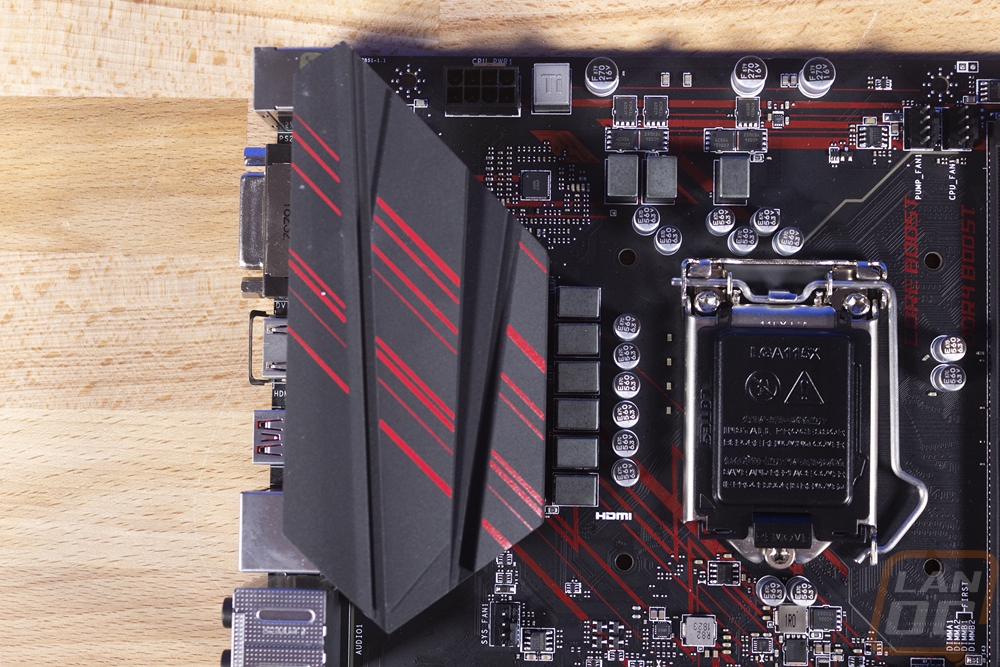
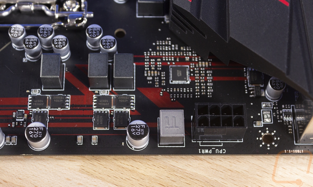
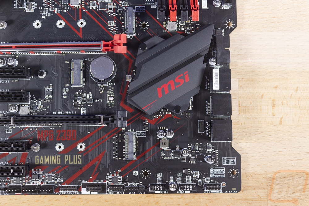
As for cooling, there are two heatsinks in total with no heatpipes or anything connecting them. Down next to the PCIe slots the chipset heatsink is low profile to fit under long video cards. It isn’t especially large. It has a flat black finish on top of an aluminum design. It is held in with two push in latches and has just a touch of red with the MSI logo and two small dashes that carry the screen printing from the board up on to the heatsink. The other half of the cooling is around the CPU socket or to be more specific just to the left of the socket. The Z390 Gaming Plus has just the one heatsink in this area. It is tucked up next to the chokes on the left covering the phases but you will notice that there are a few up along the top as well that have no cooling. Power circuitry, in general, is where this board is lacking and the heatsink while looking huge from the top is more of a canopy that bridges over to the rear I/O. It doesn’t completely cover that either though.
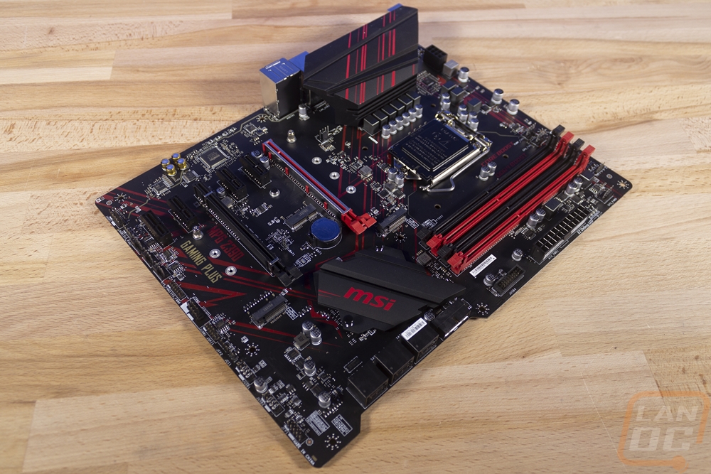
Starting in the top left corner of the board let’s take a look and see what it has going on. This area is mostly dominated by the CPU socket and the heatsink to the left of it. That said MSI did slip in one case fan header up under the heatsink and then the CPU power up along the top edge.
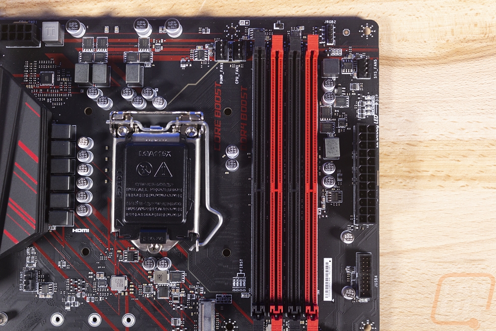
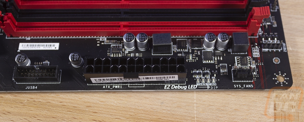
In the top right corner, there is a lot more going on. For starters this is where they have the four DDR4 RAM DIMMS, they are in a staggered red and black layout with a printed layout next to them showing that the red slots should be used first. Next, to those, there is a CPU fan header and with it a pump header then over on the right edge another header for another system fan putting the total count at 4 so far. The 24 pin has what MSI called their EZ Debug LED layout right above it, this is four small surface mounted LEDs that will show where you are in the boot process. Below all of that is a USB 3.1 internal header. Then up top near the memory is a four pin LED header.
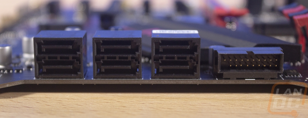
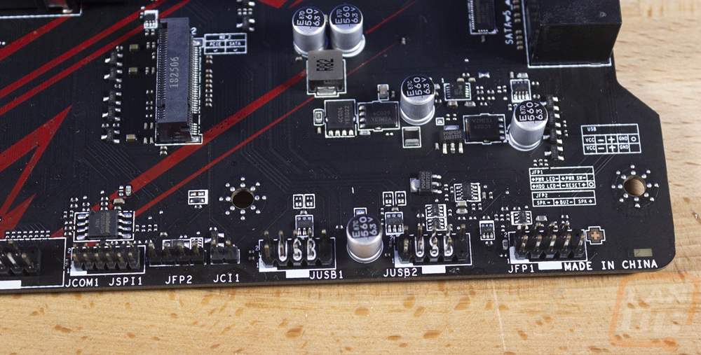
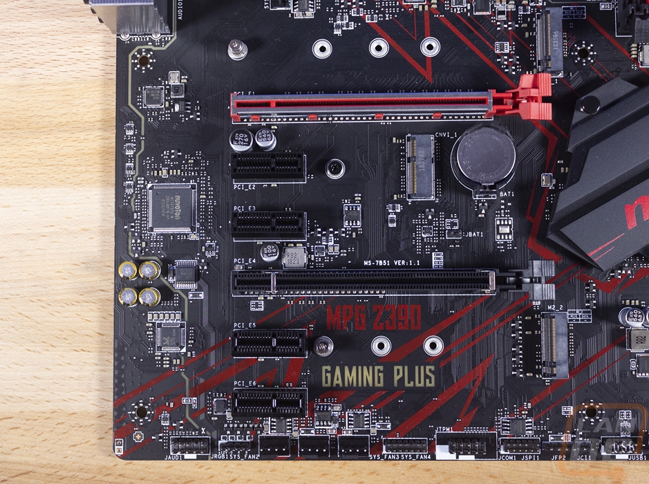
The bottom right corner also has a lot going on, even with the chipset heatsink taking up some of that space. For starters, MSI did something a little different for a budget board with the notch cut out of this side where the SATA ports are. Asus did something like this on their Rampage VI Apex but that was a high-end board. The notch pairs up with the six right-angled SATA ports as well as the second internal USB 3.1 header. This time the USB header is at a right angle like the SATA ports, both should be much easier to keep your wiring clean. Then down along the bottom edge, there are two older USB 2.0 headers as well as the front panel header right near the corner. MSI did print that layout above that one, but I would still prefer easier to see color coding. The JFP2 or front panel audio jack is all the way over on the left next to the Com port. I don’t know why it isn’t with the rest of the front port other than filling the space to make the board look fuller.
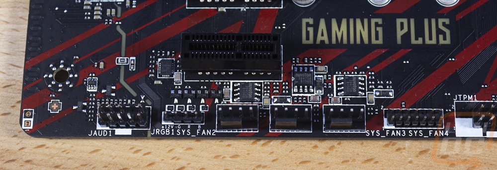
The bottom connections carry on over to the left corner. This is where you will find three more fan headers, that puts us at 7. Then next to that is a second 4 pin RGB header. Then on the left is the front panel audio jack, it is on a partially split PCB.
For PCIe options, the MPG Z390 Gaming plus has a total of 6 slots and two M.2 connections. The top M.2 is above the main PCIe slot and the second is just below the other x16 length slot. There are then four x1 length PCIe slots and two x16 length slots. The two x16 slots are listed in the specifications as full x16 slots without any notes but getting into the manual has more detail. I think MSI should have included this in the specifications though. So the red slot is a full x16 lane slot using CPU lanes. All of the X1 slots use PCH lanes and the second x16 length slot is PCH lanes AND it runs only at x4 bandwidth. So even though this board officially supports Crossfire (but no SLI) that X4 bandwidth isn’t really going to allow that. There is a third M.2 slot in the mix here as well just below the red X16 slot but this is shorter and only supports adding an Intel Wireless-AC(CNVi) module to add wireless support to the Z390 chipset.
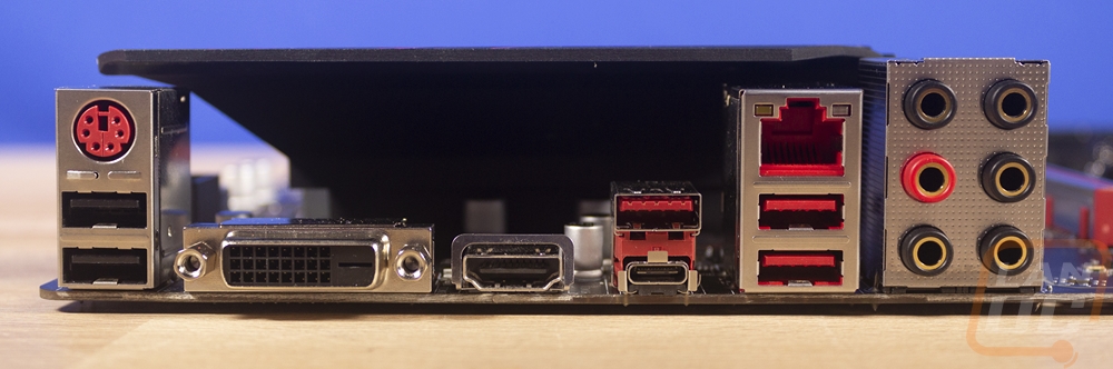
Around on the rear, I/O the Z390 Gaming plus has a big hole right in the middle, this might be the most obvious sign that this is a more budget-friendly board. On the left, you get two USB 2.0 ports with a legacy PS2 port. Then next to that for the onboard video, there is a dual-link DVI and an HDMI. Then from there, you do get a few more modern USB options. The Type-C port and the dark red port above it are both USB 3.1 Gen 2 ports. Then next to that are two normal USB 3.1 with the Intel I219-V based Gigabit LAN port. Then on the far right is the 6-jack audio layout. I personally would love to see even just two more USB ports, USB 2.0 would be fine, but I always want more USB ports, even on the highest end boards.
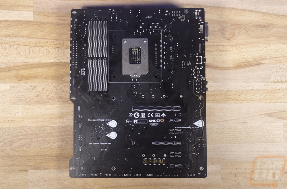
The back of the Z390 Gaming Plus does give us a better look at that flat black PCB. It is also where MSI has all of the printed logos that are required by a lot of companies. They also have those warning zones where people sometimes forget standoffs. Beyond that, we can better see the split PCB for the audio is mostly intact. Also, the notched PCB over on the other side is better seen back here.