Board Layout and Pictures
With X570 being a progression from X470 and X370 before that, I wasn’t expecting any huge changes with the design on the Crosshair VIII Hero but right from the start, you can see a few. So the change from the X370 to X470 for the Hero was mostly a change from grey to black. But the Crosshair VIII Hero, on the other hand, looks like a much higher-end board. The heatsinks are larger and they added a heatsink/cover that handles the chipset as well as the M.2 drives which also has active cooling. Active cooling on the chipset for X570 is on just about every board, but in general, this looks a lot like the crazy Alph/Omega boards making the older Hero models look like budget boards in comparison. They also have the Hero branding a lot more prominent on top of the I/O shield.
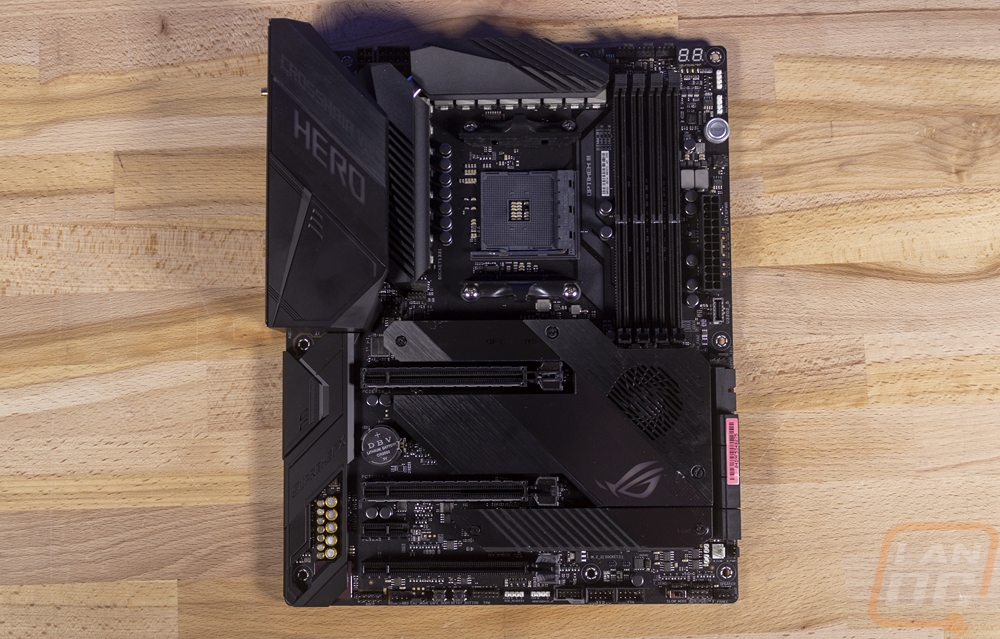
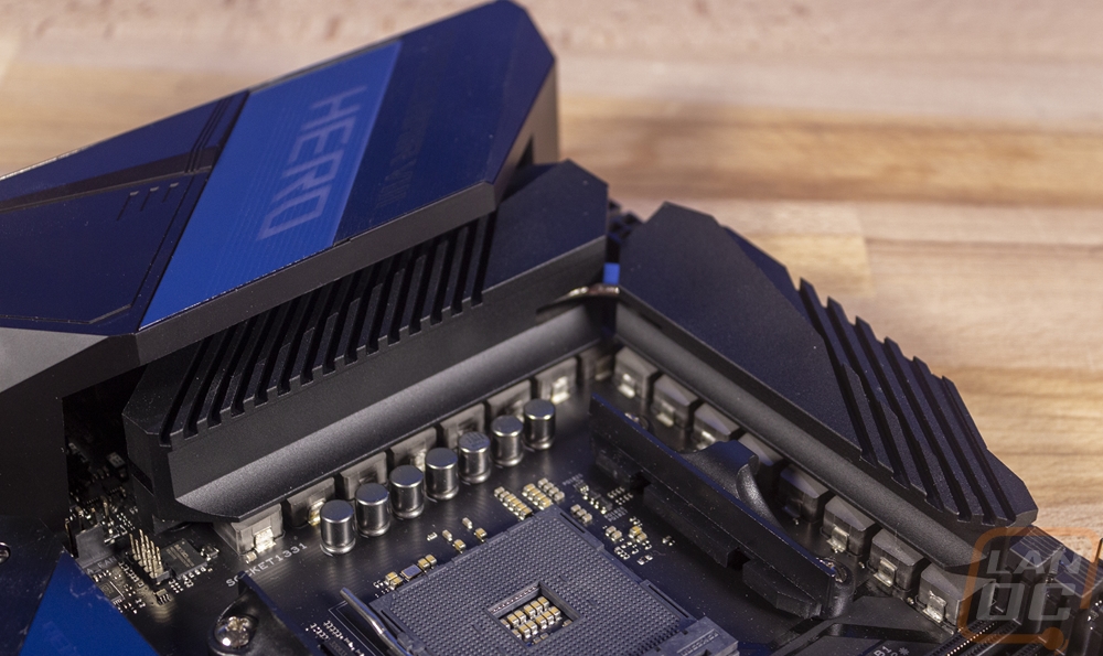
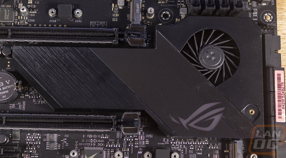
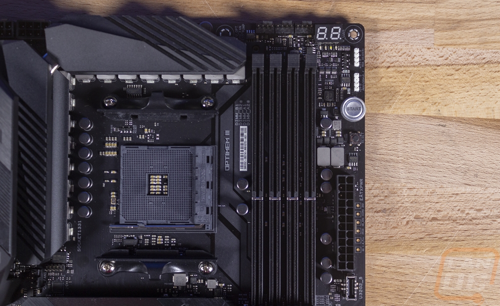
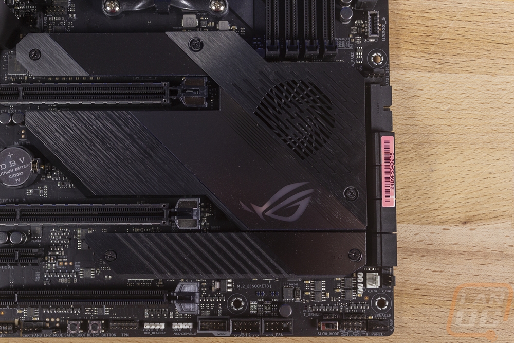
So one of the big additions for X570 boards is a big bump in power for the new CPUs, similar to what Intel boards had to do with the push to high clock speeds and core counts to keep up with AMD. You can see around the CPU socket on this board that Asus has loaded the board with as many VRMs as they could. They are running a 7x2 configuration of IR3555 VRMs which Asus lists as 16 (and you can see 16 in this picture) with two large heatsinks across them. You can also spot a heatpipe that runs between them. Then for the chipset, the heatsink is larger than before. It spreads out up un between two of the PCIe slots and has the two M.2 drive slot covers that match it. In the picture below I have those off though. The cooler has a small fan which reminds me a lot of the older X79 boards from Asus and is a custom delta superflo fan designed for 60,000 hours or more of use. This part of the cooler has an RGB backlit ROG logo as well. The cooler under the cover is designed to blow down and to the left, aimed directly at the bottom M.2 slot which will get some cooling as well.
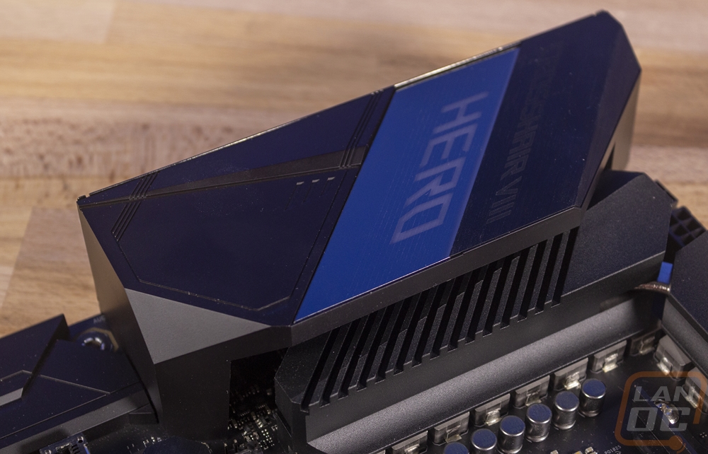
I love the I/O cover and Asus went larger on this one, you can see that it goes up over top of the left VRM heatsink partially. The cover has a mostly black finish with a silver strip across it. Just above that they have Crosshair VIII etched into the cover and then the HERO part lights up with Asus Aura RGB lighting.
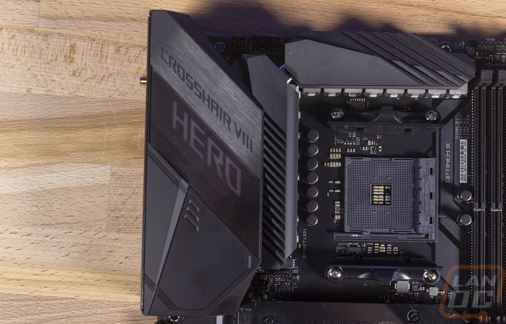
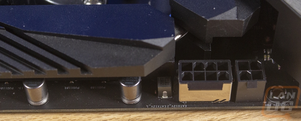
Looking a little closer at some of the features starting in the top left corner. This area is mostly dominated by the two VRM heatsinks, the CPU socket, and the rear I/O cover but Asus did slip in the CPU power connections up in the corner. The Hero has one 8-pin and then a 4-pin for CPU power. The 8-pin is interesting because they put a metal shield around the plug. This might be related to the ProCool II connectors. I’ve seen ProCool in the past where they keep the connection tight against the PCB to try to dissipate heat which is what can cause a connection like that to heat up and melt in high power situations. Right behind the I/O shield down towards the M.2 drive Asus also slipped in one 4 pin PWM fan header.
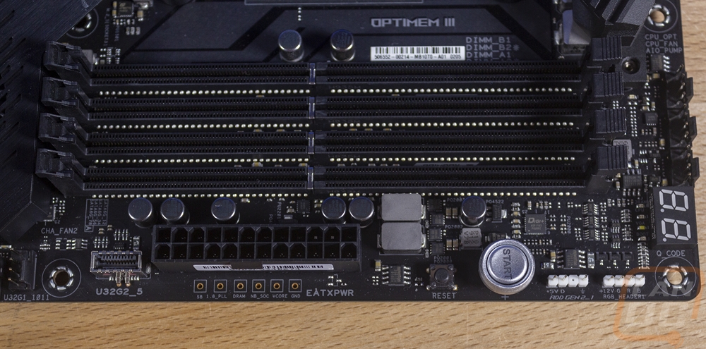
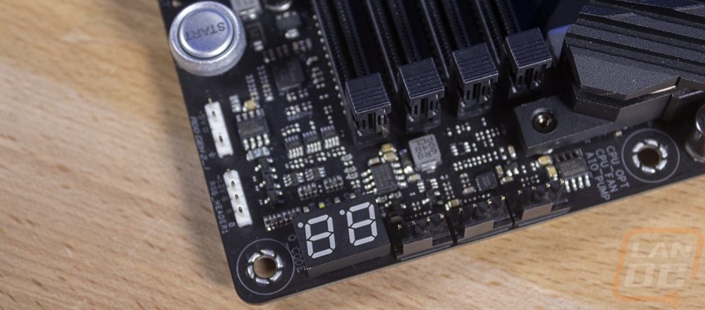
Now the top right corner of the Crosshair VIII Hero has a LOT more going on. The biggest are the four DDR4 DIMMs. They are in black plastic with metal shields on each DIMM and in normal Asus tradition, they only have clips on one end for easier installation. Above those slots, there are three 4-pin PWM fan headers. Two are CPU fan and CPU fan optional then the last header is for an AIO pump if you are running an AIO water cooling setup. Next to the fan headers and right by the top right corner screw is the two-digit status LED readout. Below that the two small white headers are for RGB lighting, the top is a normal 4 pin and the bottom is an addressable 3 pin header. Below those is a Start button for power which has an LED built in to light up the start text and with that a reset button. Then next to the memory slots is the 24-pin motherboard power which has small holes that you can stick a multimeter into to read the live voltages, each of those is labeled as well. Last but not least is a new style USB Gen 2 header so you can get a Type-C connection with proper Gen 2 speeds on your cases front panel if it is supported.
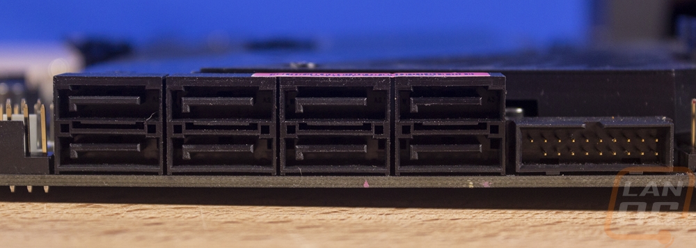
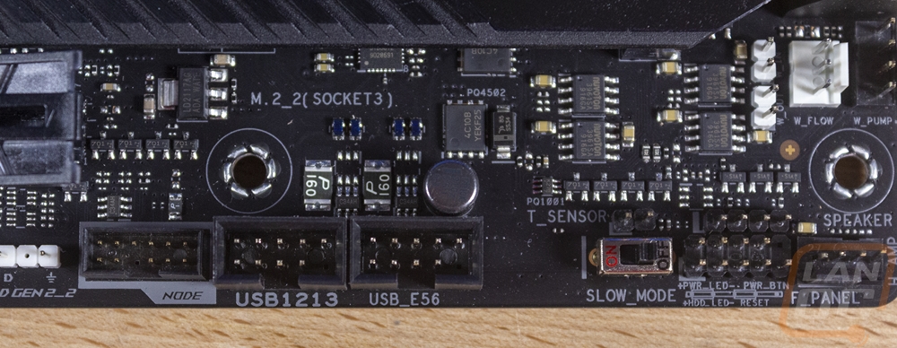
A majority of the bottom right corner is filled with that large low profile heatsink for the X570 chipset. There is still a lot of other stuff going on in this area though. Over on the right edge, there is a USB 3 header which is positioned at a right angle along with 8 SATA ports that are also all at a right angle. There is a 4-pin fan header just above that and down below the SATA ports, there are two more. One of those is a water pump header which is designed to handle the increased amperage of a pump. Next, to that, the 3-pin white header is where you can hook up a water flow meter and next to that are two 2-pin headers for thermal sensors for the water temperature in and out of your radiator. There is another temperature prob header down on the bottom as well. That is above the slow mode switch for overclockers who have boot issues to run a lower clock speed during boot. That has the front panel connections next to it. There are two older USB 2.0 headers and then an Asus Node port. This is a serial header connection for hooking up a small LED screen that will output system status information including boot codes when booting and information from Asus’s LiveDash software.
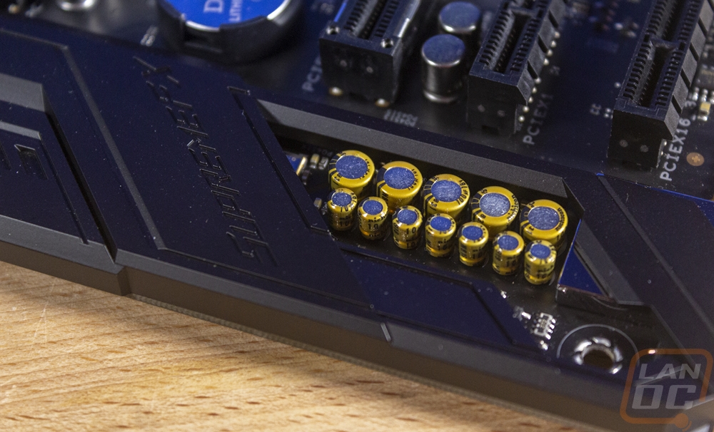
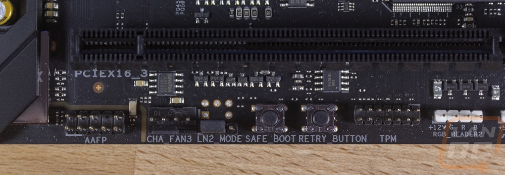
The bottom left corner is, of course, come to all of the PCIe slots first and foremost. This includes three x16 length slots and one x1 length slot. The x1 slot is notable because it is open-ended meaning you could actually install devices with a longer slot into it as long as you are okay with only getting x1 bandwidth. The top two x16 slots will run at PCIe 4.0 if you have a new gen 3 Ryzen CPU but they do split up to x8 speeds if you use both at the same time. The last X16 which you can spot because it doesn’t have a metal shield on it only runs at x4 speeds. This corner also has the audio chipset which is partially covered by a shield but you can spot the gold caps sticking out. Asus went with their ROG SupremeFX 8-Channel High Definition Audio CODEC. It includes jack detection and impedance sense for front and rear headphone outputs. It is rated at a 120 dB SNR for output and 113 dB SNR for input. It has a ESS Sabre ES9023P DAC with support for up to 32-bit 192kHz playback but that isn’t supported in 8-channel mode. Down along the bottom the audio header is on the left with a small split in the PCB filled with a resin that splits the audio chipset apart from the motherboard for less signal pickup. There is one last PWM fan header which gives a total of 8. There is a trusted platform module header along with two more RGB headers, one 4-pin normal RGB and one 3-pin addressable. Then for overclockers, there is an LN2 mode jumper then a safe boot and boot retry buttons.
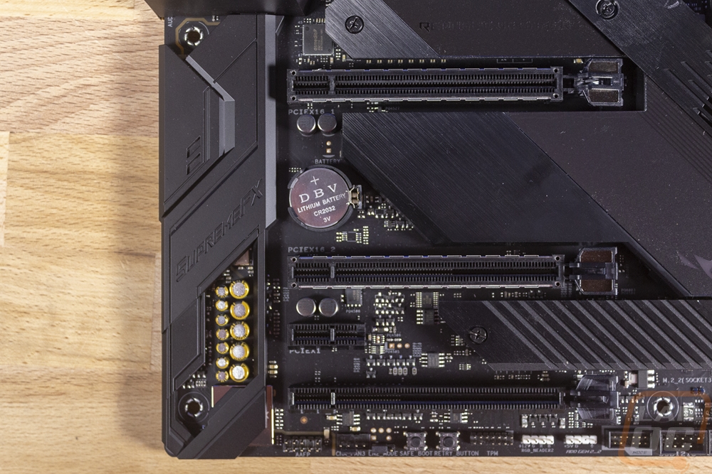
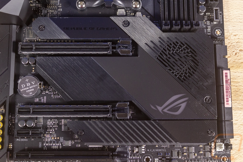
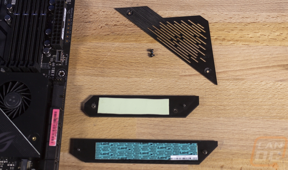
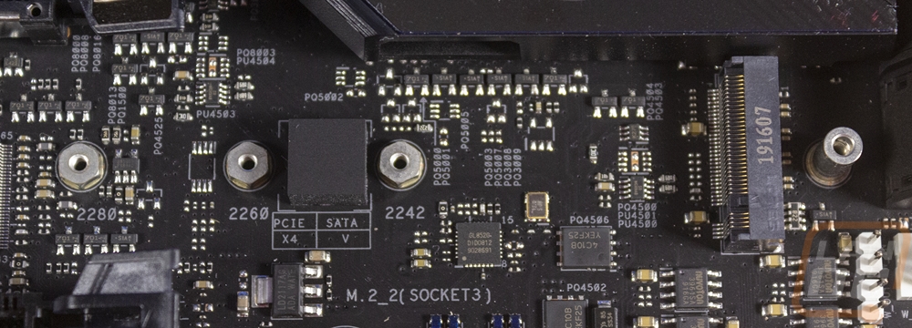
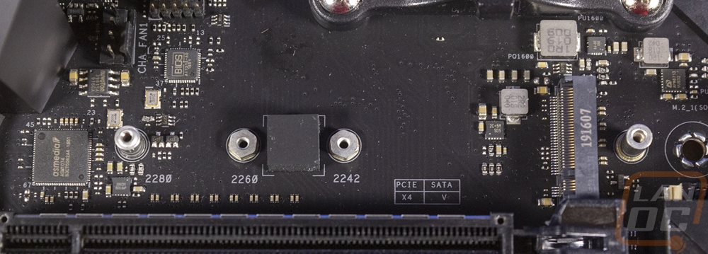
Slipped in between the PCIe slots the Hero also has two M.2 slots. Each has its own cover which holds the M.2 down and is also a cooler. With the heatsinks off you can see they both have heat transfer tape on them. Getting them off does require you to pull more off though. The fan cover runs up across the top M.2 slot for some reason which is really annoying. Especially if you decide to use one of the many SSD designs now that have their own heatsink. Both support 2242/2260/2280 length drives and are both PCIe 4.0.
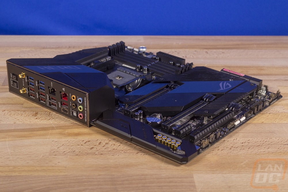
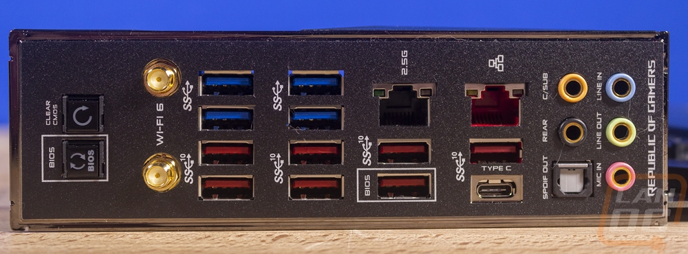
Now the rear I/O for the Crossfire VIII Hero, just like past Hero boards is completely stacked. I really wish all boards had this many connections. On the far right, you have the standard audio layout with 5 plugs and one optical connection. The audio connections are easy to spot with colored rings around each of them. On the far left, there is a BIOS update button and a clear CMOS button to make things a lot easier than having to dig into your PC. Then the middle is filled with USB connections. There are four blue USB 3.2 plugs. Then below that 8 Gen 2 ports with 7 of those being Type-A and one Type-C connection. There are two wifi antenna jacks running on the Intel Wi-Fi 6 AX200 controller. This gets you 2 x 2 Wi-Fi 6 (802.11 a/b/g/n/ac/ax) with MU-MIMO supports dual-frequency band 2.4/5GHz. Then there are two wired network connections. One if an Intel I211-AT which is the red plug and the black is using the Realtek RTL8125-CG 2.5G LAN.
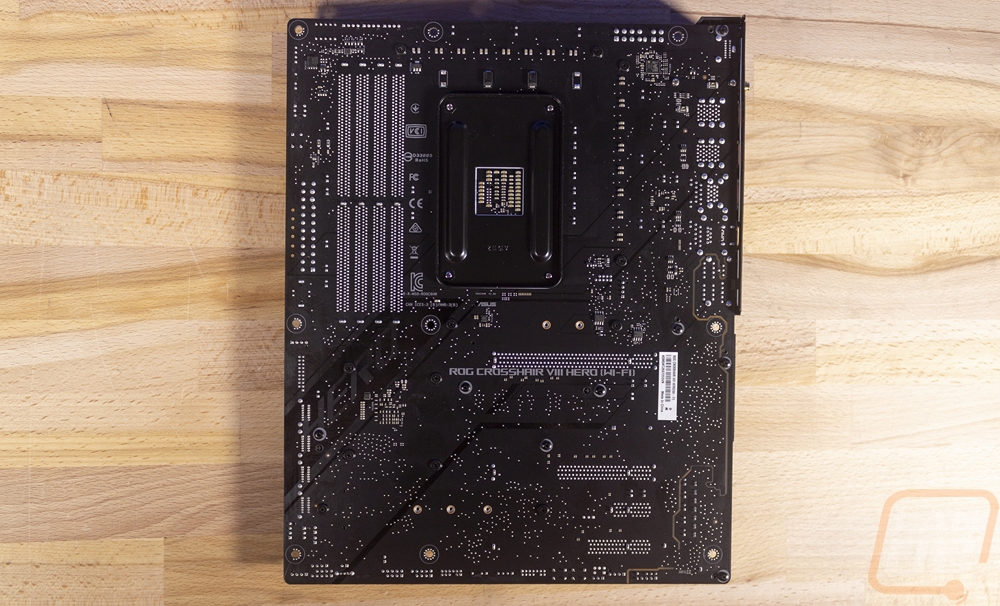
The back of the Hero does a good job of showing just how packed the board is. Beyond that there isn’t too much going on, there aren’t any hidden M.2 slots or anything back here. You have the standard AMD backplate for the CPU. The PCB is flat black with some gloss black accents back here as well. You can also better see the split PCB for the audio with the lin running around the front panel connection at the bottom around the sound chipset then along the edge up to the rear I/O where the rear audio jacks are.