Board Layout and Pictures
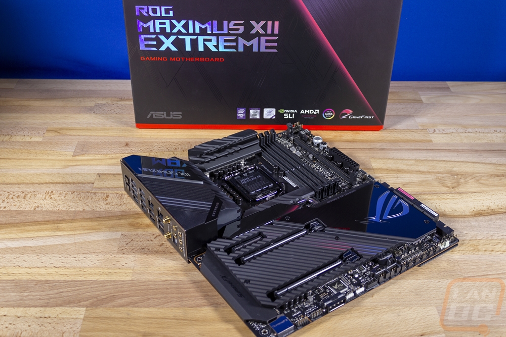
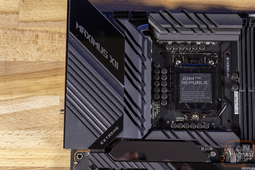
The ROG Maximus XII Extreme, being Asus’s highest-end Z490 board is packed with hardware. So much so that they went with an eATX layout which is wider than standard ATX. The board measures at 12 inches tall and 10.9 inches wide. Being a high-end board it is also extremely heavy which is a combination of the multiple heatsinks and the large shield's front and back but also higher-end boards like this tend to have thicker PCBs with a higher copper percentage as well. This board specifically has an 8 layer PCB, the Aorus Master and MSI Carbon that I’ve taken a look at both had 6 layers. It all adds up to a board that will surprise you when you pick it up, even before you install any hardware on it. It has the standard flat black PCB but from the top point of view, you can hardly see the PCB at all. It is covered in heatsinks which are all in a flat black aluminum with V shape gives in the top with the exception of the mirror finish on the chipset cooler. Overall the board looks mostly blacked out with mirror finishes used as accents
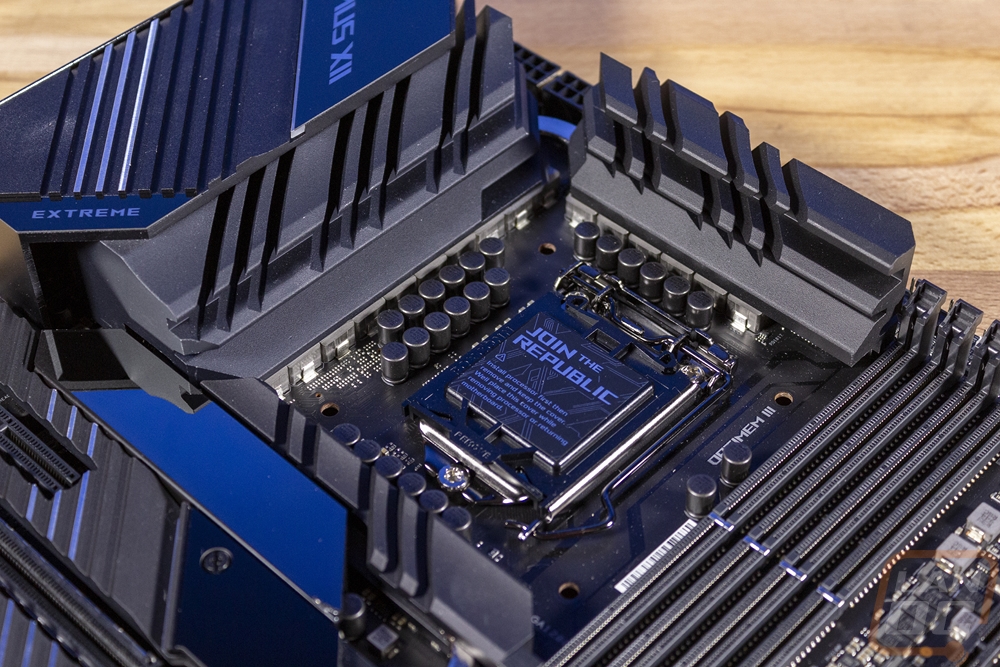
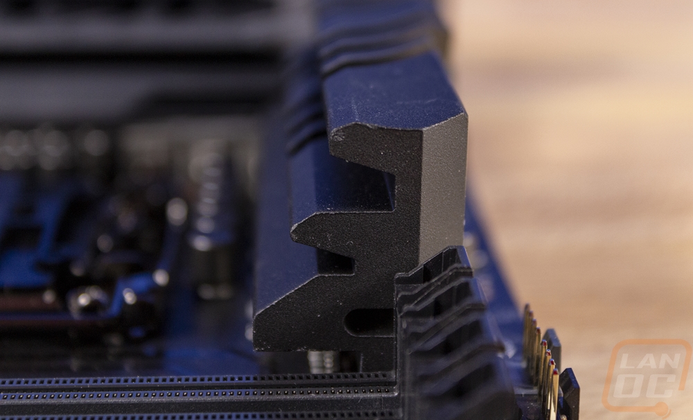
Like I mentioned before, the ROG Maximus XII Extreme has a lot of passive cooling built-in in the form of heatsinks. SO much so that they make the board extremely heavy. This includes three different heatsinks that are around the CPU socket. These are tied together with a heatpipe and all three help handle the VRMs and power circuitry. The Maximus XII Extreme has 16 Vcore VRMs which are teamed, as well as two VCCSA’s and two VCCIO but Asus did decide to skip out on any for the onboard GPU as well which if you think about it using a $750 motherboard with onboard video does seem a little crazy. 16 is a little crazy as well, but it does match the highest end board from Gigabyte but overall is most likely more than should be needed. The three heatsinks for power circuitry have grooves cut into them for additional cooling as well as an extruded shape that adds groves on the sides as well.
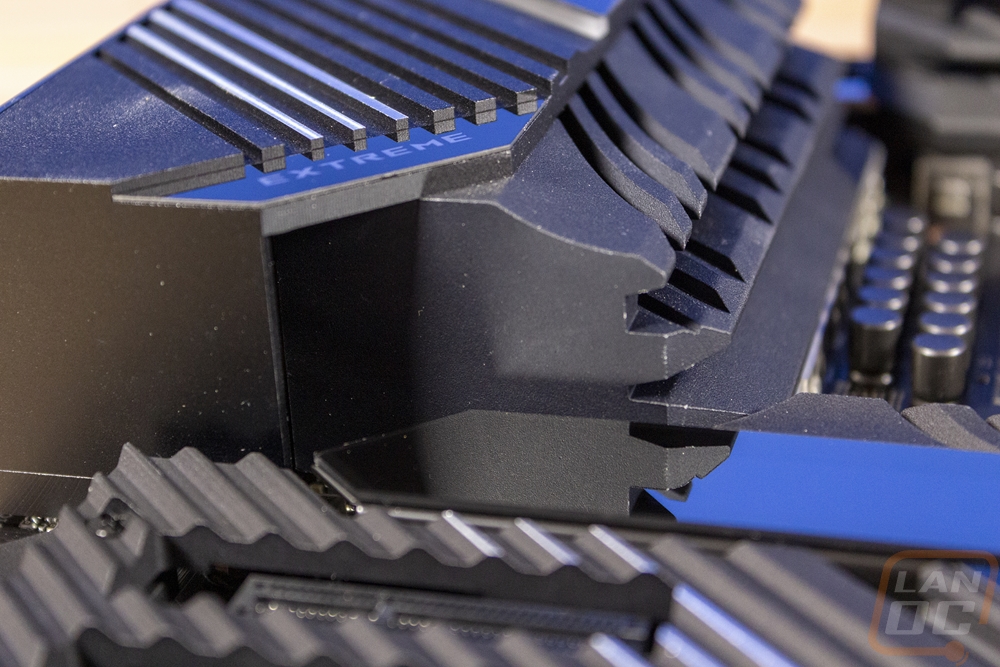
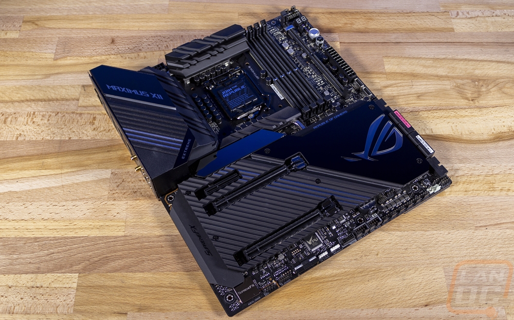
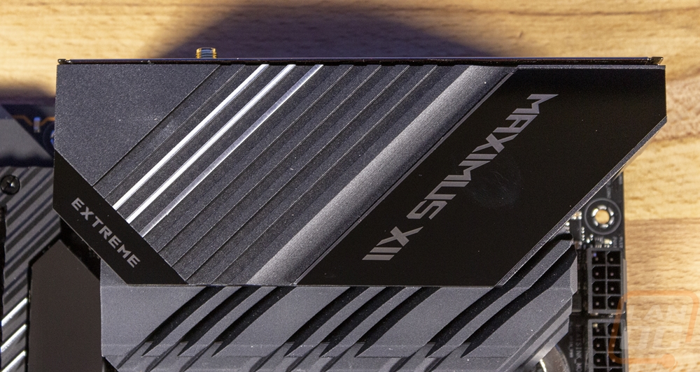
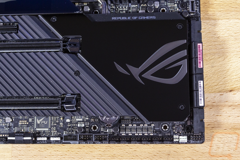
The cover of the rear I/O is also integrated into the cooling as well and it is aluminum, not plastic like all of the other boards. It also has the mirror finish at the top and bottom where they have the model name. There is also a small strip of addressable RGB lighting up under the Maximus XII branding that ties in with the rest of the board's lighting.
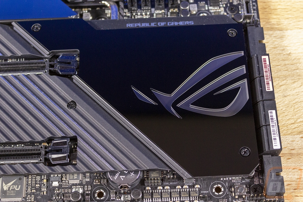
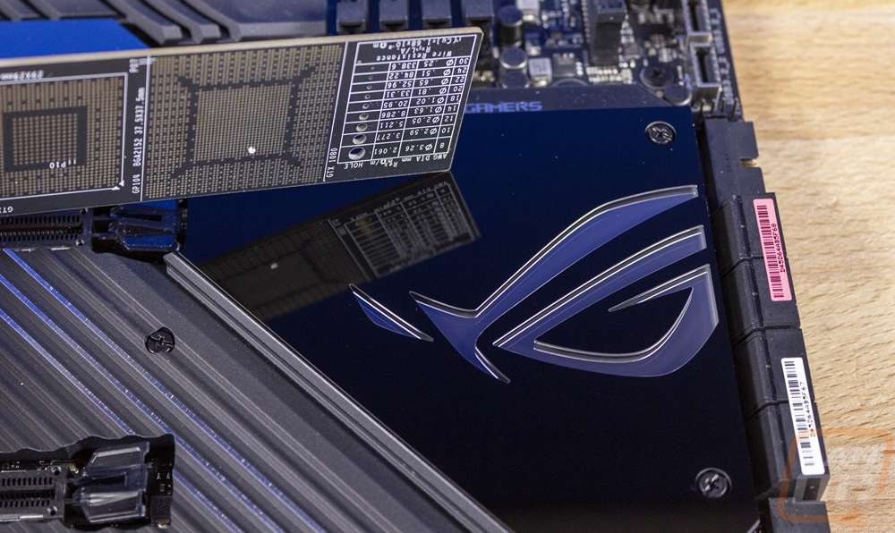
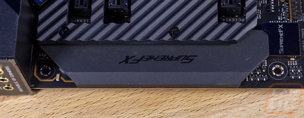
The rest of the cooling covers up nearly the entire bottom half of the board. This includes the chipset cooler which is on the right side with a black finish and a mirror ROG logo cut into it. Then on the left, there is one large removable panel that covers all of the M.2 slots and helps distribute their heat. The left side is thick aluminum with a flat black finish with the exception of three of the ribs that have a chrome finish.
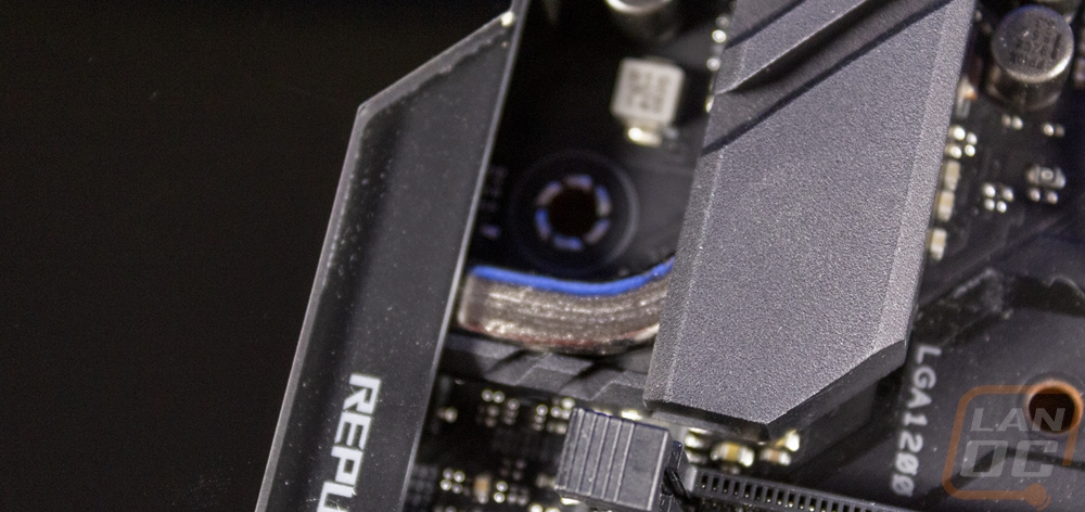
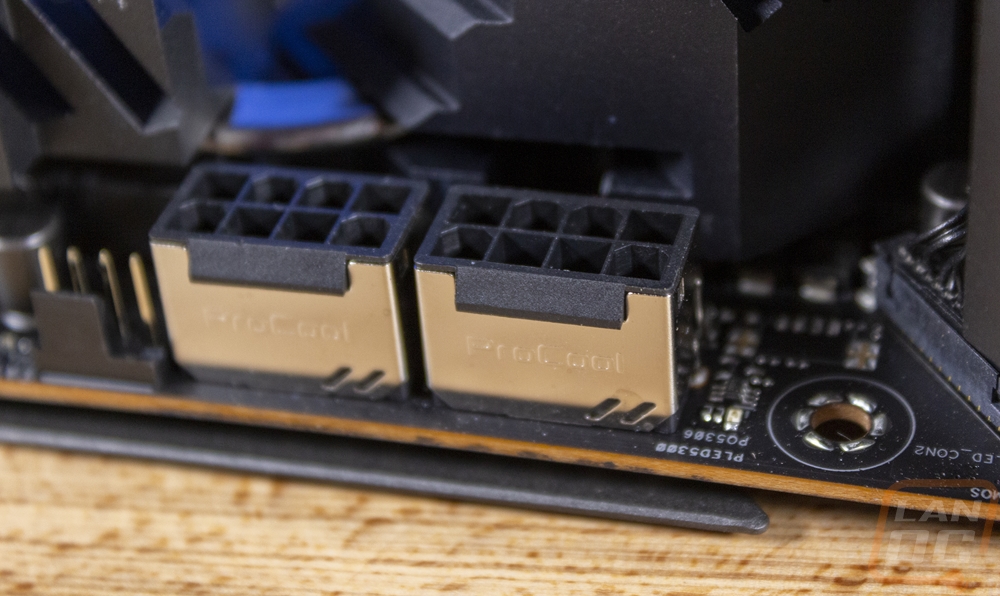
So let's take a closer look at the board features a little closer to see what all is hidden starting up in the top left ¼ of the board. This area is always packed full with the rear I/O and the CPU socket but with the three heatsinks, it is tighter than ever, not to mention the I/O cover also hanging up over top of the VRM cooler. Below all of that there is a reflective area and Asus integrated one of their Livedash OLEDs. Asus has been putting these on their more expensive boards for a while now but they are getting bigger and bigger. I will say I did notice that ours came in damaged in the right corner but the screen itself works well. It can show post codes and temperatures as well as other information like frequencies, other temperatures, and even gifs or images. Being up above the video card it should be visible in a traditional vertical case layout as well. Up on the top edge, they also have a four-pin fan header that sits next to the two CPU power connections which are two 8-pin power plugs. These are Asus’s Procool II connections which have that metal shielding around the outside and pins that are solid and they say fit tighter. Loose connections cause additional heat and that heat will melt things down when you are pushing the limits.
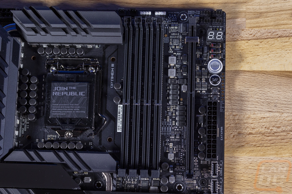
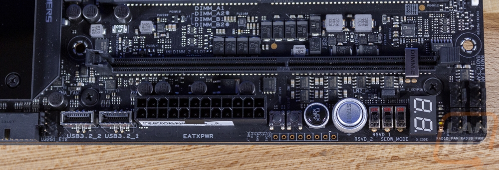
In the top right, we start getting into a lot more, but before that, I have to point out just how packed every bit of the OCB is in between everything. Like between the four DDR4 DIMM slots (which have metal shielding as well as the single latch design that Asus likes to use) and the DIMM.2 slot. The DIMM.2 slot works with the included riser card to give the ROG Maximus XII Extreme two more M.2 slots which are out away from the heat and more in line with airflow. Do up on the top edge the two white headers are for RGB lighting, one is a four-pin traditional RGB connection and the other is a three-pin for addressable RGBs. There are two PWM fan headers to the left for the CPU and optional CPU fans and then there are FOUR more in the top right corner which are labeled for radiator fans. Just below that there is a POST code display in addition to the livedash which does the same and right above that if you look close you can see four surface mounted LEDs that light up during the boot process to give you a clue if you have a boot failure. Then between that and the 24-pin motherboard power connection you -will find a whole array of switches and buttons. The three switches turn on overclocking features for LN2 like slow mode. There is also a jumper next to those for LN2 mode. Then below that is the large backlit start button for power and a flax button which is also backlit that can be programmed to do multiple things. The small buttons are for safe boot and a retry button that will reboot with your previously failed overclock. Then down at the bottom, there are two of the new USB 3.2 Type-C headers.
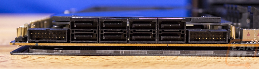
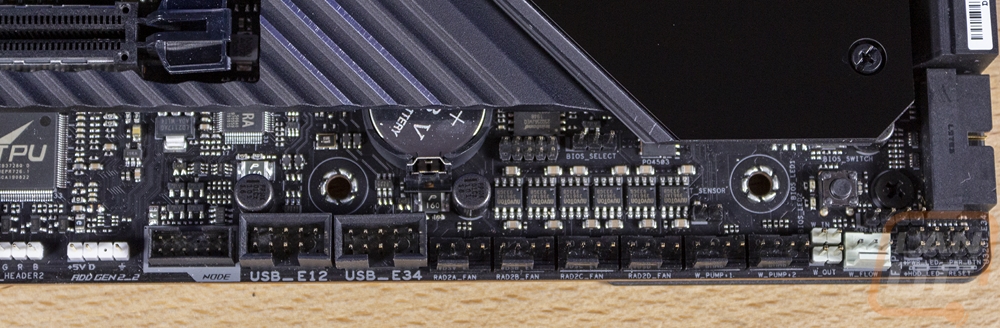
Down in the bottom right portion, we once again have a large heatsink covering up a lot of the board. But along the right edge, there are eight SATA ports which all face out at a right and then two USB 3.2 headers that do the same as well. There is also a 4-pin PWM fan header as well. Then down on the bottom edge, you will see another whole line of 4-pin fan headers. This is the water cooling zone as they call it and you have four more fan headers and two water pump headers as well which when combined with the others (these are the last we will find) far puts us up to 14. Which is more than I’ve ever seen. I’ve built systems where I had to add fan breakout boards to power the fans, I wish I had 14 back then! Also in the water cooling zone are a pair of 2-pin headers for water in and out temperature readings and a three-pin header next to those which is for a water flow sensor. The front I/O connection is in the far right corner and Asus did include their Q connect to make that easier but it does also have labels under the header if needed. The small button in that area is the BIOS switch which has two LEDs next to it to show you which BIOS chip you are currently running on. There is another 2-pin thermal sensor plug in black as well. Along the bottom on the left, there are two USB 2.0 headers, which I have to admit is good to see with there still being devices like fan controllers and lighting that sometimes used them. Then the Asus Node connection can be used with a few Asus devices but specifically for this board, you would most likely use it for the fan extension card II which gets you six fan headers, three temperature probe headers, and three RGB headers that can all be hooked up back behind your motherboard tray. Now I’m sure you are wondering why you would want this with the 14 fan headers the board already has, well you could be building a wind tunnel or hovercraft or maybe you just want to keep your wiring cleaner and hide it all.
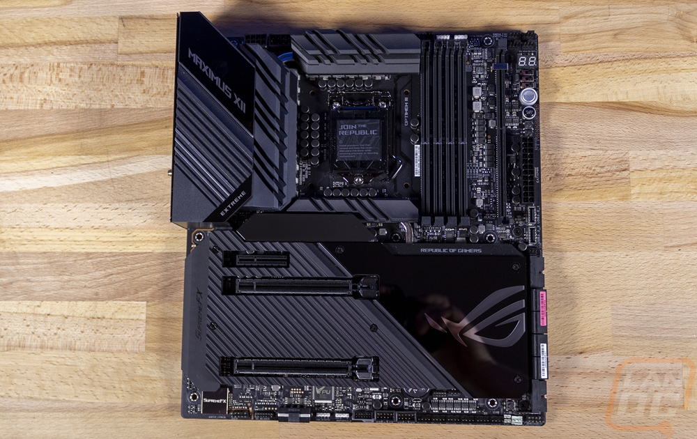
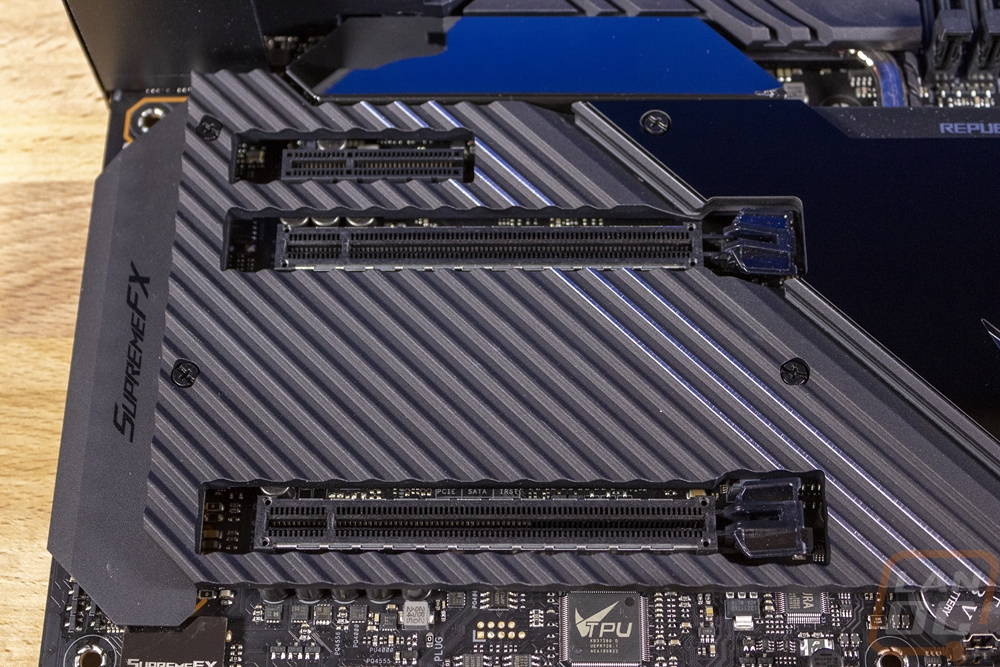
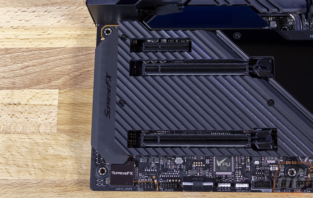
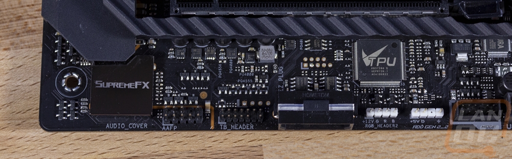
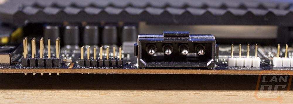
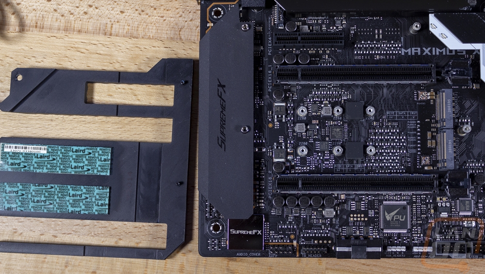
Last but far from least we have the bottom left portion of the Maximus XII Extreme. This of course has the big heatsink that covers the M.2 ports which I will touch on in a second. But that also goes around all of the PCIe slots and you might think a crazy board like this might have 10 maybe 20 PCIe slots but Asus has kept things simple, mostly thanks to Intel’s lack of CPU lanes with just three slots. Up top is a x4 slot that has a unique design that Asus likes to use which is open-ended and could technically fit a longer card if that big heatsink didn’t black that. Then there are two x16 length slots which are spaced out with two slots between them so even with a 2.5 slot video card there will be a little airflow room between it and the bottom slot. Now all three slots are PCIe 3.0 which is what Z490 officially supports. Asus isn’t marketing PCIe 4.0 support, but they have at least confirmed that many of their Z490 boards “have been engineered with PCIe 4.0 readiness” and I would like to think their flagship would be included in that readiness. The lane breakdown is x4 for the top x4 slot and the first x16 slot gets full x16 if the bottom slot isn’t in use and if they are both being used they both get x8 which is the standard layout on most Z490 boards. Down on the bottom edge, there are also a few more connections. Namely the front panel audio connection on the left and the TB header next to it. There is a Molex power connection for feeding additional power to the PCIe slots and then two more RGB headers, one being a four-pin traditional style and one 3 pin addressable. Which gives the Extreme a total of two normal RGB headers on the board, three more on the fan extension card and two addressable RGB headers as well so if lighting is your thing you should be good to go!
Taking the M.2 heatsink and shield off is only a few screws away. Pulled off you can see that the heatsink does use thermal pads to help the thermal connection. They also have both M.2 slots in that large gap between the two PCIe x16 slots which does mean both are up under any large video cards you use and that heat from the video card will affect them. The DIMM.2 riser card is the better choice. Both are PCI 3.0 and x4 as well as the DIMM.2 slots as well but only the top M.2 slot also supports SATA as well. Those are getting rarer to see with cheaper NVMe drives being available for a while now.
For onboard audio, everything is covered up including the controller down at the bottom. Asus did still split everything on to its own separated PCB with the resin gap between them. It also has an ESS ES9023P DAC capable of 112db DNR /-94dB THD+N. They are running the S1220 Codec which along with the DAC provides 10 channels to allow the rear 7.1 playback, an independent 2.0 channel, and multiple stream stereo to the front panel as well at the same time. The gold Nichicon CAPS aren’t visible but they are up under the shield as well. They also went with switching MOSFETS that allows impedance sensing to be used on the rear jacks or the front panel connection.
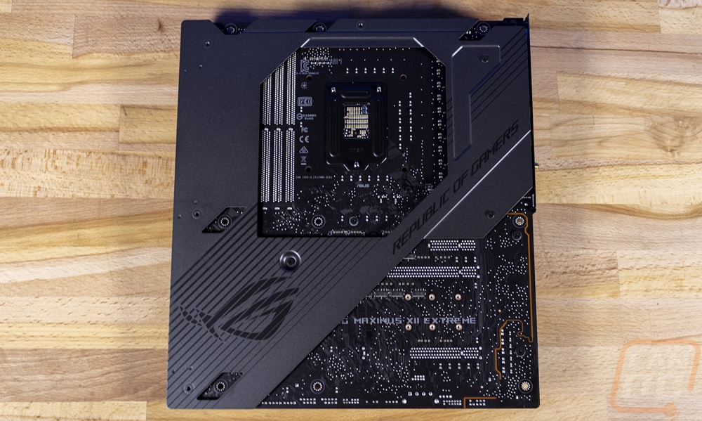
The back of the Maximus XII Extreme has a large metal backplate which helps protect it from damage and adds even more strength (and weight) to the board. But the bottom right corner is still left uncovered so we can still see the split PCB for the onboard audio well here and the black PCB which looks packed even on this side with all of the traces visible.
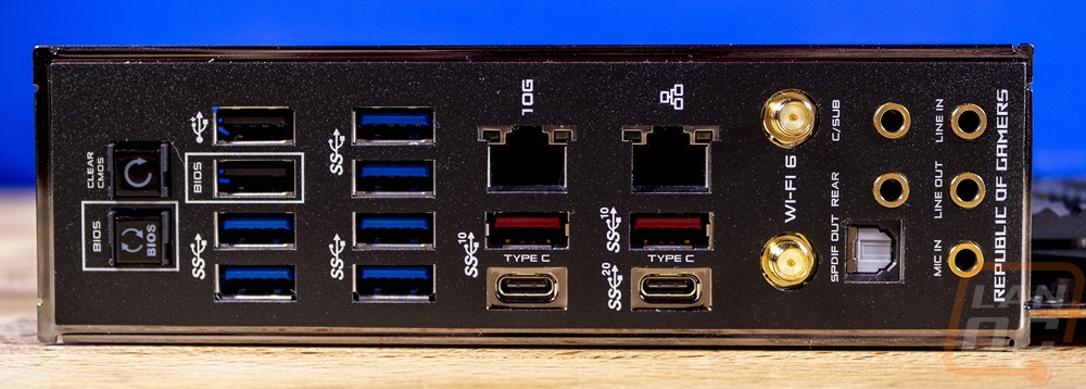
The rear I/O is one of those make it or break it areas for me. I personally have to have a lot of USB connections and a lot of expensive boards skimp in that area to make room for more marketing tag lines. Asus didn’t do that here though, in fact, they completely cut out onboard video and opened up more room for USB ports. You get two full stacks of ports, six of which are blue USB 3.2 ports. The two black ports are older USB 2.0 and one has the BIOS name next to it because this is the port you use when you want to update your BIOS without even having a CPU or memory installed. You use the BIOS button which is on the left. Also with that is the clear CMOS button which is nice to have on the outside of your build. Over in the middle, there are two USB Type-C connections which are nice to see. Not just the one that most boards have (plus the two headers inside as well and two more on the included Thunderbolt 3 card). The bottom right Type-C is a USB 3.2 Gen 2x2 or a superspeed 20Gbps port which is the fastest USB port you can get (and still have the speed of the two Type-C Thunderbolt 3 ports on the included card). Then the other Type-C is a normal SuperSpeed 10 or Gen 2 port. The two red Type-A plugs are also Gen 2 as well. Above that are two network ports. The one on the left is a 10G NIC running on the Marvell AQtion AQC107 10Gb NIC and the other is the stock Intel I225-V 2.5G NIC that comes with Z490. Next to that are the two WiFi 6 antenna plugs which run on the Intel AX201 controller. Then on the far right is the audio layout which looks a little cramped but is a normal 5+optical layout. Each plug is labeled and has gold connections but when the board is powered up they also have color-coded LEDs inside which are amazingly helpful in the dark at a LAN or back behind your PC under your desk.