Board Layout and Pictures
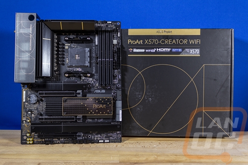
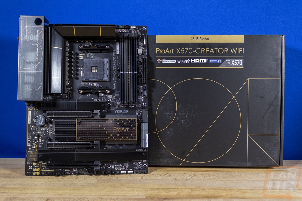
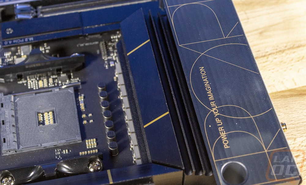
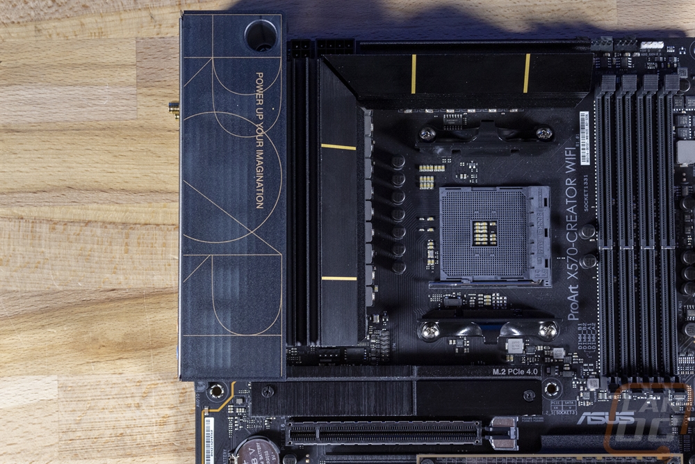
I mentioned before that the ProArt X570-Creator WiFi has a completely different look than Asus’s other lineups like their ROG gamer-focused products. The ProArt X570-Creator WiFi’s styling is squared off and shares the same styling as the box which uses all black with gold trim. In fact, the rear I/O cover on the ProArt X570-Creator WiFi even has that same thin styled font used to put Pro Art on the board. While I do sometimes like the “gamer” styling, I think this is one of the best looking AM4 boards out because it takes a break from that and keeps things simple and clean. The ProArt X570-Creator WiFi is a full ATX board and from the look of things Asus has filled the board up so there should be a lot to check out once we start looking closer.
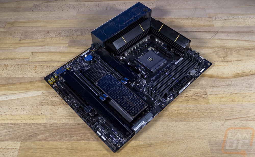
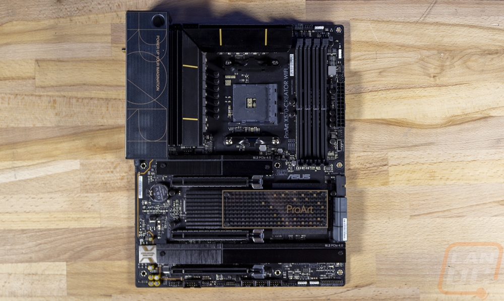
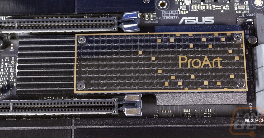
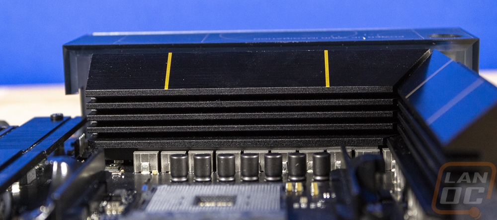
For cooling the ProArt X570-Creator WiFi starts with a large L-shaped heatsink for cooling the 14+2 teamed power stages situated above the CPU and to the left of the CPU. This heatsink has slots on the inside facing the CPU socket and then rounded groves on the outside for additional surface area. It then is anodized black with gold accents to match the rest of the board. The chipset has a smaller heatsink that runs from the SATA ports up in between two of the PCIe slots. This heatsink has a transparent panel on top of 2/3rd of the heatsink that adds the ProArt branding in gold. Then all three of the M.2 slots also have their own dedicated heatsinks which are simple aluminum plates finished in black with thermal pads to pull the heat out from an SSD.
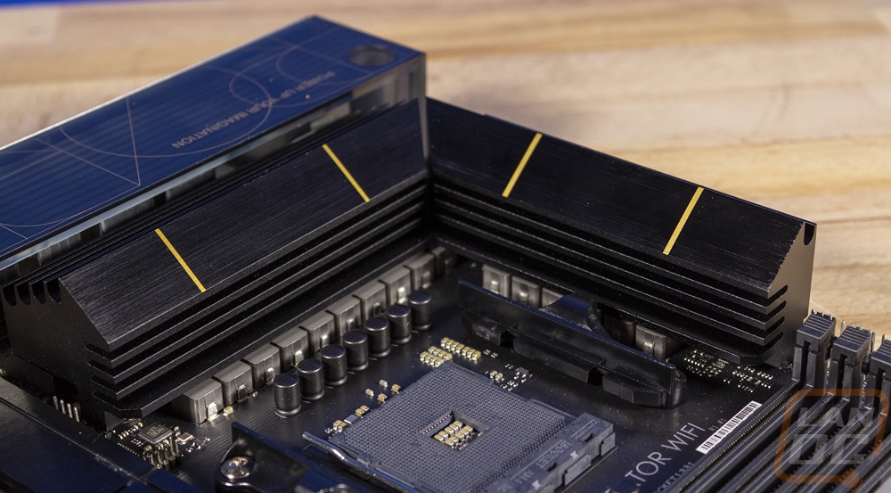
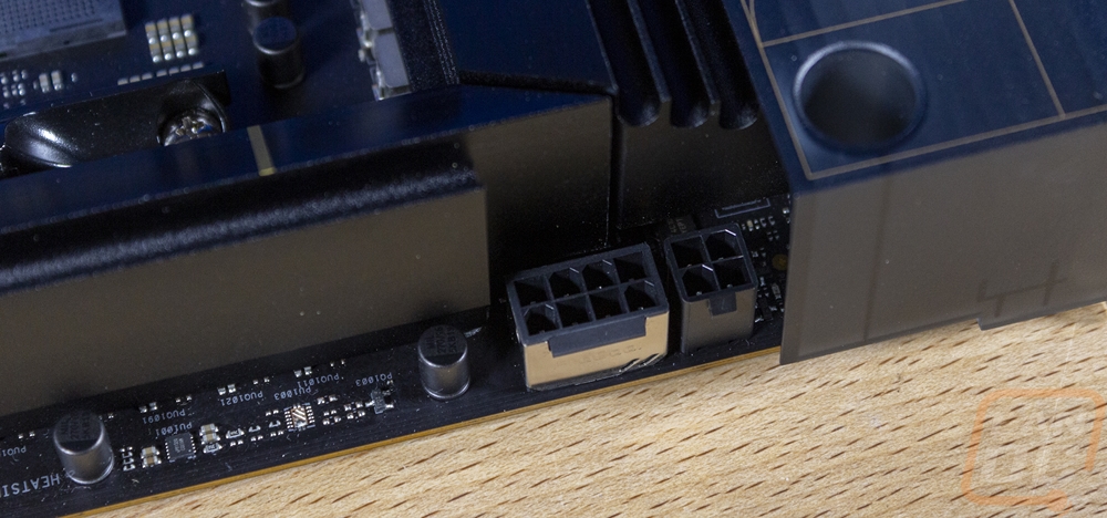
Starting in the top left corner of the ProArt X570-Creator WiFi to check out some of the board features. This area is mostly filled with the rear I/O which has a cover over it and the CPU socket and the VRM heatsink. But this area does have the dual CPU power connections tucked away up in the top corner, one being an 8-pin and the other a 4-pin. It is hardly visible, but just below the VRM heatsink, there is also a four-pin PWM fan header tucked away there.
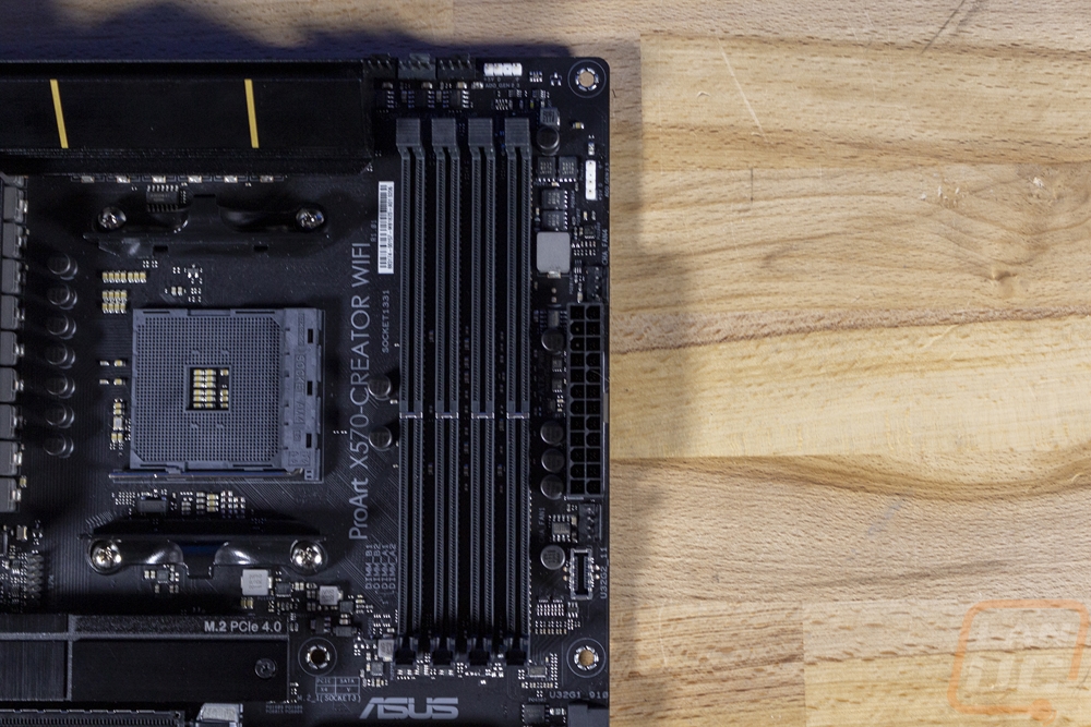
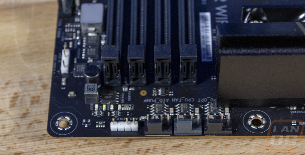
The top right on the other hand has a lot more going on, starting with the four black DDR5 DIMMS to the right of the CPU socket. Asus has also slipped in the full ProArt X570-Creator WiFi model name screen printed on the PCB between the two. Up along the top edge, there are three 4-pin fan headers, two are for the CPU fans and one is tagged for an AIO pump. There is an addressable RGB header to the right of those which is bright white and easy to spot then there are four small status LEDs that help diagnose boot issues between the RGB header and the memory DIMMs. There is a second addressable RGB header on the right side and two more fan headers, one above the 24-pin motherboard power and one below. Below that the ProArt X570-Creator WiFi does have one newer Type-C USB 3.2 Gen 2 front panel connection as well.
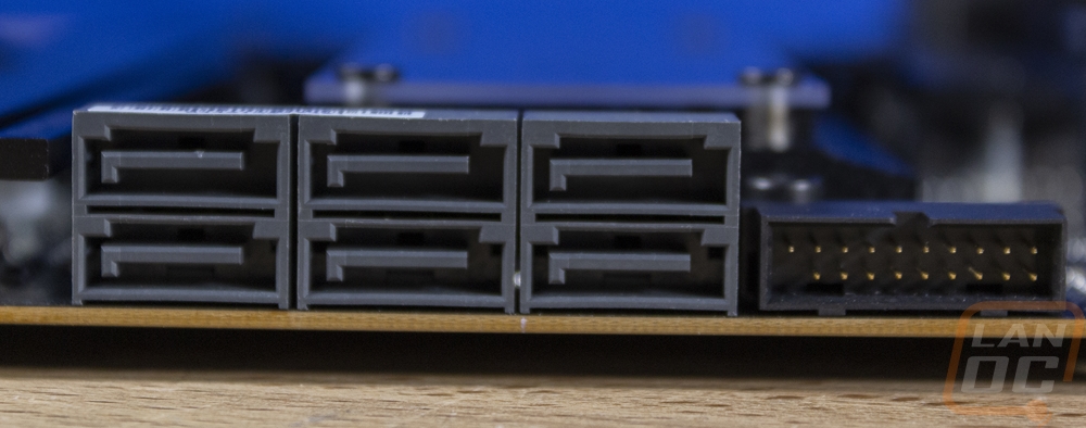
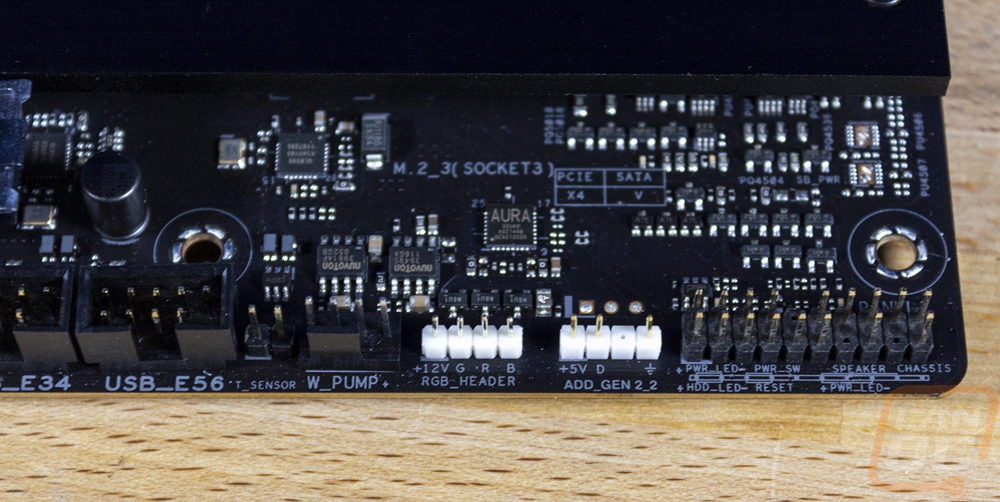
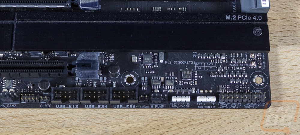
The bottom right corner has the chipset cooler and the doubled up M.2 slots which run to the end of the board. But beyond that, it has a right-angled USB 3.2 Gen 1 header sitting next to the six right-angled SATA plugs. Then along the bottom edge in the far right corner is the front panel connection. In addition to the helper that is included with the board, all of the front panel connections have labels printed below the plug including the chassis speaker, and from the looks of things it has two power LED options. To the left of that are two more bright white headers. The three-pin one is a third addressable RGB plug and the one on the left with four pins is a standard 12v RGB header. Next to that is a water pump plug which is another 4-pin fan header connection that is designed for the extra amperage and a two-pin thermal sensor plug. The ProArt X570-Creator WiFi doesn’t come with any external thermal sensors, but you do have the option to add one. Then near the middle of the bottom row, there are three older USB 2.0 headers which is huge because a lot of devices like RGB or fan controllers still use these not to mention some cases for their front panel connections.
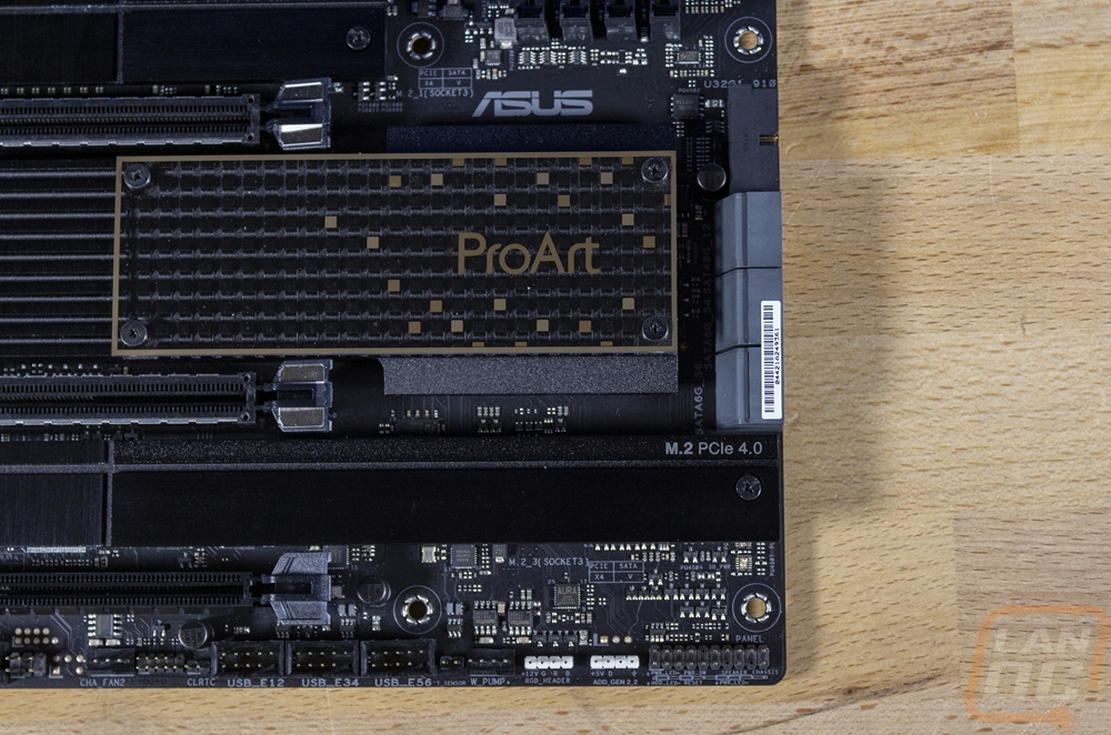
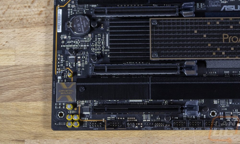
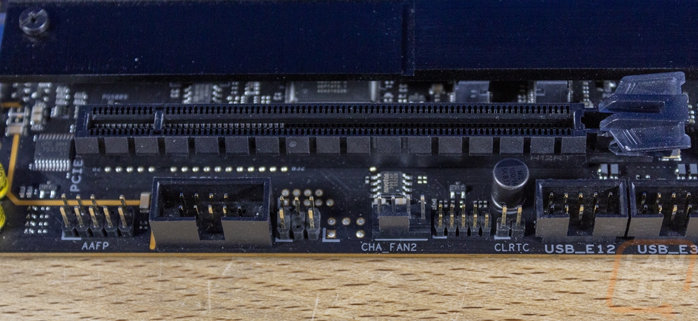
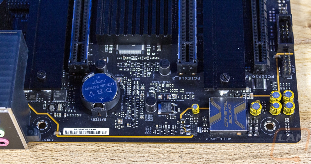
Finally, in the bottom left corner, the ProArt X570-Creator WiFi has its PCIe slots. It has three full x16 length slots and the top two run off the CPU. For newer CPUs that support it, that will be a single x16 PCIe 4.0 slot or dual x8 slots or for older CPUs, those will be PCIe 3.0. The bottom slot runs off the X570 chipset and runs in x4 mode. The second slot does share bandwidth with the M.2_2 slot so when this is the case the slot will run in x4 mode. There is one M.2 slot up above the top PCIe slot and then two tip to tip below the second that runs across the whole board. The M.2_1 and M.2_3 slots have dedicated lanes and all three M.2 slots are capable of x4 bandwidth, PCIe 4.0 if supported, and SATA. The M.2_1 and 2 slots use CPU lanes and the third slot runs off the chipset. On the left Asus has a dedicated area partitioned off for the onboard audio. The split PCB design helps keep interference down. This runs on the Realtek S1220A CODEC and is 7.1. It also has impedance sensors for the front and rear to automatically switch and internal amps for headphone use as well. The gold caps are Nichicon caps which is nice to see as well. For connections along the bottom edge on this left side of the board, the front panel audio is on the far left to keep it close to the onboard audio circuitry. There is then a COM port, one last four-pin PWM fan header (for a total of 8), and then the clrtc which is the CMOS clear header.
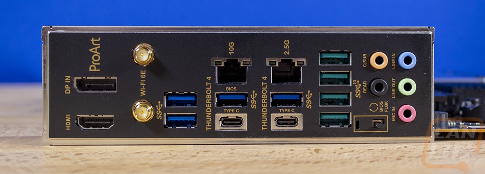
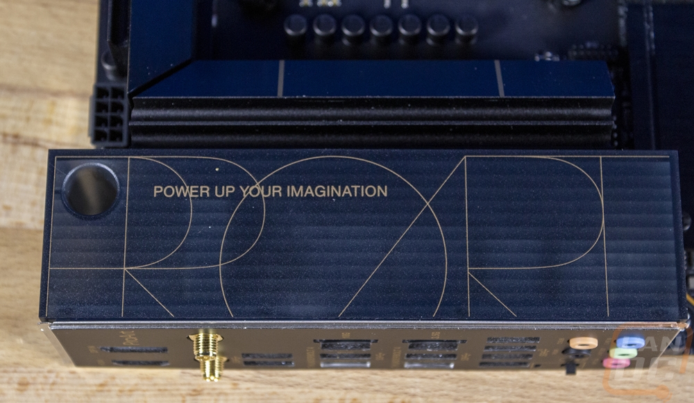
For the rear I/O, the ProArt X570-Creator WiFi does come with the I/O shield pre-attached and along with that, the entire rear I/O has a plastic cover on the top. The cover is plastic and has a tinted translucent look that matches the blacked out look of the board but gives a slight peek behind the shield as well. For the I/O connections on the left, you have an HDMI port which works only with CPUs with a built-in GPU, and above that is a DisplayPort which is an input used to pass through display to the Thunderbolt 4 connections. Next to that, they have two antenna connections for the built-in 2x2 WiFi 6E as well as the Bluetooth v5.2. From there you have two USB 3.2 Gen 1 ports stacked and distinguished by their blue color. There are two more of the same 3.2 Gen 1 Type-A connections to the right sitting below the network connections as well. For the network connections, there are two, the one on the left is a 10G running on the Marvell AQtion AQC113CS controller and the one on the right is an Intel I225-V 2.5G NIC. At the bottom of both of those stacks, there are two Type-C connections, both are Thunderbolt 4. Then to the right of that is another stack of USB ports, four this time which are all a blue/green color. These are the faster USB 3.2 Gen 2 Type-A connections. Then to the far right, the ProArt X570-Creator WiFi has the normal audio connections minus an optical connection which has been replaced with the BIOS Flashback button for updating the BIOS even without a CPU installed which is helpful in situations like this where you might be running a CPU that came out after the launch of the motherboard.
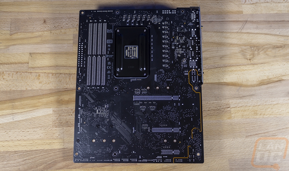
The back of the ProArt X570-Creator WiFi gives us a much better look at the blacked out PCB. The CPU socket has the standard metal backplate and tucked between that and the memory Asus has a lot of the normally required logos printed to keep the rest of the board clean. The back view also lets us see the split PCB around the audio circuitry as well.